Difficult to say why it is the way it is from that picture. A few things come to mind. There is an existing slab and another was poured against it. After curing, the shrinkage resulted in the crack you see. OR, it could be poured on top of an existing contiguous slab that had a step up for whatever reason, and a topping was poured to level the surface, same curing process, same shrinkage.
The texture of the concrete looks different one from the other.Like older concrete and a smoother concrete.
But I cannot see that far away ;)
In any event, they do make caulk for this type of joint and you should use it to fill that crack.
Weird, it was all built at the same time, the slab is concrete, and so is 6" of the lower outer walls. This was exposed once the floor was pulled, so like you said it must have been curing. In any case, I wouldn't be benefiting from this Brien? I have some hardcore concrete caulking I can use, darn I thought it may have been a blessing, but looks like a lil more work hehe. :wink:
Cracks, in general, look like cracks in concrete. This looks more like an area where concrete was mated up to an existing pour. It could be where, depending on the size of the overall slab, Part was poured in one day and the other the next. This would create a straight line, like in the picture, where the two separate pours did not bond due to curing.
Thing is, I cannot say how or what or why it is like it is without seeing the big picture. If it is two separate pours, then they could well be not touching, and you get your blessing. But, depending on the what and hows of it, there could be wire mesh that is a connection between the two. The blessing may still be partially received.
Can't see, can't tell.
HEY EVERYONE!!!! I apologize for not being on here too much over the past 2 months or so, I recently started work again, and with this damn economic situation in the states, I'm pushing for every penny. Yet, that has not meant that I have ceased the progress on my build. I have been able to work on it at least one day a week so far, so lemme give you all the rundown, of what I have been doing.
I have been carefully caulking in the air gaps between my frame floor plates and the concrete slab, using a GE concrete caulk, which I must say does the job very well.
I finished my custom made blocking for the entire ceiling perimeter, (the 2x6 blocks against the roof eaves) allowing for the OSB to be installed on top of the joists, and sealed.
- I went with the OSB for my outer leaf ceiling, due to the fact that the rest of the builds outer leaf is already OSB as well, I figured it was best to match the densities.
I have began to install the OSB. (see pics & captions) Unfortunately, my existing trusses make it impossible for a clean install, so I will have to cut 12 1/4" pieces to fit between them, which will be held from the top by 2x4 blocks.
NEXT: After the entire layer of OSB is layed down, I am thinking of caulking all gaps around the parameter, and the seams from the bottom, the top seams I will use some liquid nail to allow the OSB sheets a bit more reinforcement without moving, when walking on top.
I will then be scoring and installing 1/2" gypsum on top of all the OSB, offset from the OSB seams, allowing for a better seal. Then tape, mud, and caulk all gaps and seams.
Guess it looks like the HVAC will be moving in shortly as well, I believe I have found a prime location for the unit, which makes it incredibly feasible to run short ducts to my iso booth, live room, and drum room, since the space is right above. Hopefully this will save me a little extra $$$.
Brien - I was able to find out about the slab of the structure, since we were discussing to caulk or not in the space that separates the slab from the walls. Apparenty the slab was poured in first, a believe it was 4'. Then the concrete base for the walls around that next. The curing processed separated the two, and runs around the entire structure of the building. The gap spacing runs from maybe a mm or two, to about a cm, and is deeper than 1 foot. I have no instrument currently to be able the measure the full depth of the gap, what are your thoughts on that, still caulk??
As always thanks for taking the time to check in on my thread, and feel free to correct me if I'm doing anything wrong hahaha :wink:
Ian
Anyways on to the pics -
"still caulk??"
Still caulk. Something specific to concrete joints.
Glad to hear you are back with the gainfully employed. It does make a diffence doesn't it! And your build is looking great.
Brien
Xspace- sorry to Hijack thread.
Is the reason you wouldn't lay plasterboard directly on top of the studs due ONLY to the fact that people would be walking up there?
If there was no access to above the ceiling, would plasterboards on top be ok???
[EDIT]- I just re-read everything and answered my own question. :)
[EDIT]- I just re-read everything and answered my own question. :)
Maybe not so much even walking, but just laying on the sheetrock stretched out trying to nail or screw it in place, can be enough to break it under weight. Maybe not your weight, but some of these guys ;) But that is my only reason for the suggestion.
Just a quick question for everyone,
I'm looking for a way to seal the small air space in my truss angles, in between the support plates. A caulking gun is too large to get into the gap, and others (who do not know if this forum) have recommended a spray foam, but I highly doubt that it will do the job. Is there any kind of putty or clay I can use, preferably something I can work with my fingers to make it fit in.
Thanks, Ian
Hello People, while I'm waiting on my HVAC friend to stop by and go over some things with me, I wanted to propose a few of my ideas, to see if I'm in the ballpark with any of this. First is my conduit run for my audio.
I hope I'm not going overboard here but I'm running a total of =
28 XLR studio ties (8 drum booth, 16 live room, 4 Iso),
8 XLR returns (4 drum & 4 live)
12 TRS returns (4 drum, 4 live, 4 iso) 6 of which will be used for headphone cues
12 TRS sends (4 drum, 4 live, 4 iso)
*As well as midi in/out, usb send/return in both the drum booth and live room
*Each room will also be outfitted with its own 20" monitor (via VGA's most likely) with the main computer screen in the control room as the brain
*I will be using Dsub (DB25) 8 channel snakes, which all returning will be mounted in a plate, and sent via Dsub again to a patchbay in the CR. (note drum booth and iso, will be sharing some same conduit)
*I will also be running a conduit line from the front to rear of the control room, which will be housed underneath a rear deck for connection to an effects rack behind the engineer.
If I am correct will I be needing a total of 3 separate conduit runs per room? LV audio in one, Headphones in another, and data in the third (VGA, USB, MIDI)?
I plan to use breaks in the conduit to decouple it from room to room, but, with so many connections returning to my control room, will I be jeopardizing a large amount of sound isolation, since multiple conduit returns would require a larger housing return in my control room wall???
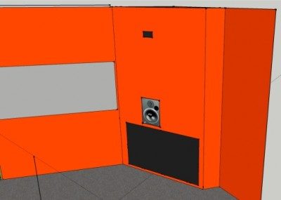
My next proposal/idea is for my soffits. I will be mounting Event Precision 8's, at a 45 degrees from the listening position. I have forgotten and cant seem to pull up the rules from prior threads on this, but what is the ruling on positioning due to modes? Basically, what is interpreted as the midpoint of the soffit (not the acoustical center) - center of the woofer? center of the tweeter? the base height of the speaker? I just want to make sure my speakers will not be in a null, I'm short, so I'm hoping Im safe. :wink: What do you guys think??
28 XLR studio ties (8 drum booth, 16 live room, 4 Iso),
Is 8 going to be enough for your drums? I often use ten or more mics on a drum kit.
My next proposal/idea is for my soffits.
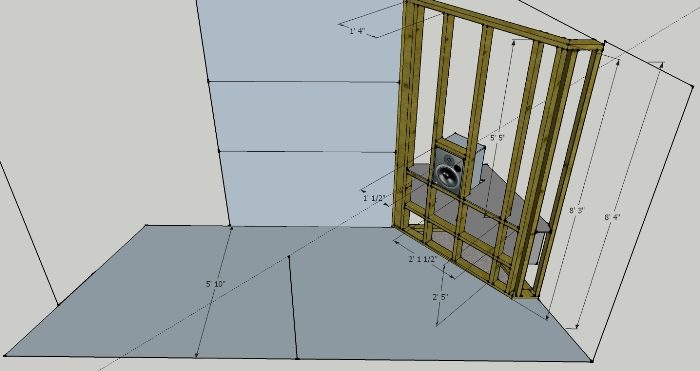
Maybe it's just me, but your speakers seem to be awfully low down! If I'm reading your diagram correctly, the bottom of your speaker is at 2'5" above the floor, which is about 73 cm. That place the acoustic center at maybe 93 cm above the floor (guessing, since you don't show it on the diagram), but normal height is about 30 cm above that (about 1 foot higher). The acoustic centers of the speakers are supposed to be at the same height as your ears, and pointing directly at them. When I'm seated at the mix position, 95 cm is roughly chest height. Do you plan to sit on the floor while you mix? :)
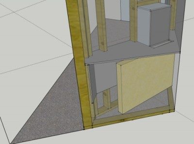
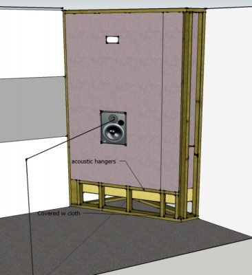
Also, there doesn't seem to be much soffit below the speakers at all! All I see below it is very deep absorption, then below that, nothing at all! There seems to be a large empty space there. If you take a look at John's design, he extends the baffle down nearly to the floor, and just puts a thin layer of absorption (plus cloth cover) over that. Maybe I'm not understanding your diagram right, but it seem like you don't have that. If I recall correctly, John places the absorption there mainly to deal with reflections coming off the rear of the console, but the baffle still goes down almost to the floor. John leaves a small gap at the bottom for the hangers that are behind the lower soffit panel.
Anyway, those are my comments, FWIW.
- Stuart -
Stuart - thanks for gettin back to me so quick, The soffits did seem low to me. I redid my drawing so hopefully it's getting better.
I remeasured my ear height which is 48."
The event 8's measure 16" top-bottom, I guesstimated the acoustical center (since contacting Event is no longer an option) to be between the woofer and the tweeter, which would put it at 12" from the bottom of the monitor. (Note in the picture the tweeter is aimed exactly at ear position: this is false, the true line would match directly from between the tweeter and woofer)
This brings my speaker base - floor to 2' 11 1/5"
Could this still be wrong, I mean I am a short guy, only 5'6," and 48" is my ear height while am sitting in my desk chair :shock:
I am I missing a step here??
And looking at Johns baffle again, I see what u mean by extended almost to the floor, would using MDF over wood for the baffle still enable me to achieve the same effect you think?
Well, the EBU says standard listening height is supposed to be 1.2 m, and wouldn't ya know it, but 48" is 1.22 m! So I guess you are a kind of "standard EBU listener", give or take an inch! :)
So if your acoustic axis is at 48 inches above the floor, and the acoustic axis of your speakers is 12" above the bottom of the speaker, then the bottom of the speaker should be at 36" above the floor. "This brings my speaker base - floor to 2' 11 1/5"" Sounds close enough to me! Call me a liar for 4/5 of an inch" :)
would using MDF over wood for the baffle still enable me to achieve the same effect you think?
I reckon it should. The baffle needs to be as massive and rigid as possible, so thick MDF should do it. John uses 5/8 plywood plus another layer of "timber finish" on his diagram. He uses that above the speaker, then 5/8 plywood plus absorption plus cloth below the speaker, down to 12" off the floor, which is the gap for the hangers. So it seem to me that if you put 16mm MDF (or even 22mm) below the speaker, behind the framing, that would leave the space between the framing for the absorption, and the space behind the MDF for hangers. To me at least that seems to approximate what John shows in his diagram.
- Stuart -
Your last drawing looks like a plan, nice drawing too.
The baffle should, indeed, be AROUND the whole speaker. That means it should also extend (if possible) southwards. Remember; active speaker radiate heat on the back. Don't forget to put an airflow behind the speaker (pref. an active flow)
Well, the EBU says standard listening height is supposed to be 1.2 m, and wouldn't ya know it, but 48" is 1.22 m! So I guess you are a kind of "standard EBU listener", give or take an inch! :)
I took a look at your latest post on your thread, what great info that EBU document was, thanks for sharing. This also must mean that "standard EBU listeners" are short guys too!! :D
So if your acoustic axis is at 48 inches above the floor, and the acoustic axis of your speakers is 12" above the bottom of the speaker, then the bottom of the speaker should be at 36" above the floor. "This brings my speaker base - floor to 2' 11 1/5"" Sounds close enough to me! Call me a liar for 4/5 of an inch" :)
If my acoustical center is at 48" and my ceiling runs about 100", will this pose any problems, since the acoustic axis will be extremely close to half the height of the room???
Ro
Thanks for the encouragement. I studied Johns soffit model drawing, and some of his sketchup files, to try and imitate it. I indeed realize that my baffle should extend downward as far as possible, I decided on replacing the plywood with MDF, and using gypsum as a finish over the baffle, which should still remain durable and rigid enough for the soffit.
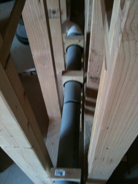
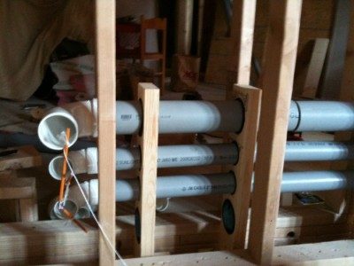
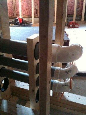
Hey guys, been busy making the green to allow me all the free time to work on the studio after october, just thought ide share with you a few pics from what i have been doing in my spare time with my conduit runs, lemme know what ya think.
Hey Everybody,
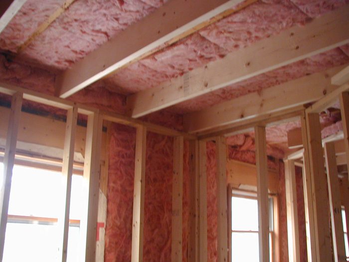
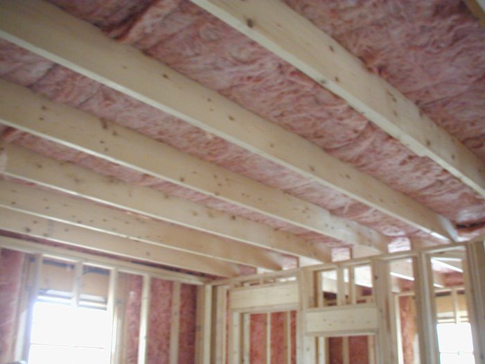
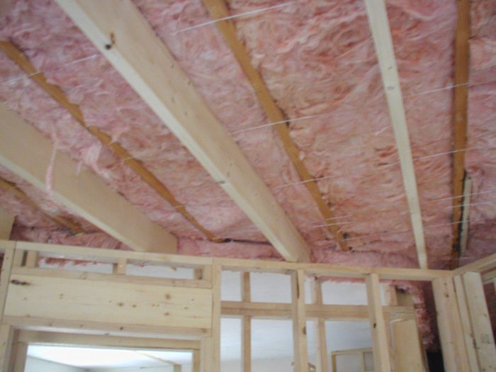
I hope everyone is well, and is making great progress on their projects. I apologize for my absence but, work had me going full throttle. Luckly my job is seasonal and allows me to work on my studio 6 months out of the year!! :D Anyhow, I have been continuing with my construction quite a bit as of late, I would like to share it with you all. Since I last posted I was able to -
Finish the and seal the ceiling for the outer leaf
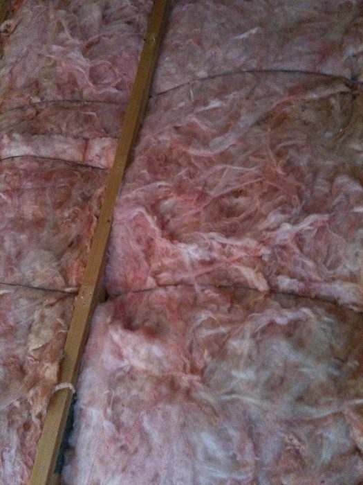
Insulate the outer leaf
Finished installing the ceiling rafters in each room
75% done with my conduit runs for audio
In the next month I am looking to have my HVAC unit installed, all electric (star grounded) finished, windows pulled out, and duct silencers made, crossing my fingers. It is a slow process, but I'm really trying to take the steps to build correctly. I do have a couple questions if anyone has the time to take a stab at them ;
1) I created breaks in my conduit for my audio cables at the entrance/exit to each room, I then wrapped the breaks with something similar to a carpet underlay - a very thick, yet breathable fabric. I then used cable ties around that, in order to keep the conduit in place. Is this acceptable, or should I choose a different method for wrapping my breaks????
2) I read recently on here recently, if I'm not mistaken, that filling the air space between 2 leafs completely with insulation can increase isolation between rooms? Is this true, or does there need to be an actual gap of air? I have so much R-19 I thought I couldn't use because I thought that I absolutely needed an actual gap of air between the inner and outer leaf's insulation.
Well now for a few updated yet boring pics :lol:
great conduit work.
Look exactly like your design :mrgreen:
1) as long as the carpet underlay doesn't creat a flanking path. Do you need anything though?
2) This is the hot debate atm- If you have it spare (all bass traps finished??..soffits...ceiling clouds???)
and again it doesn't create Mass/ flanking path between leaves. there is benifit to "spring" vs "air"
PS- if you don't have it spare- I believe the benifit vs cost gives a minimal result. So don't waste money
Thanks Lil, it's so nice to be back, and your build looks great!!! Any chance you can point me in the direction to where some of these new disputes have been going on with the "spring vs. air?" - I thought they were both the same
http://www.nrc-cnrc.gc.ca/obj/irc/doc/p ... /ir818.pdf
Top of page 24 in the above linked document: "It was assumed that thermal and practical requirements for the insulation would normally require the cavity to be completely filled and so only completely filled wall cavities were tested."
This is only one place of several I have been trying to round up. The above article deals specifically with the exterior of a residential structure so it is not the answer yet, but suggests that it was considered [filling of the entire cavity] part of a valid test procedure.
In the end I believe that everything Lil mentioned is part of the process as well.