Echo Bar Recording Studio Build Diary

Discuss studios designed and built by others.

Moderators: Aaronw, John Sayers

ricotrex
Posts: 62
Joined: Tue Oct 12, 2010 3:58 pm
Location: Los Angeles

Re: Echo Bar Recording Studio Build Diary

Post by ricotrex »

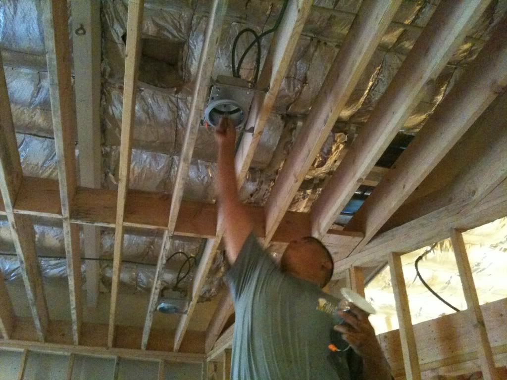
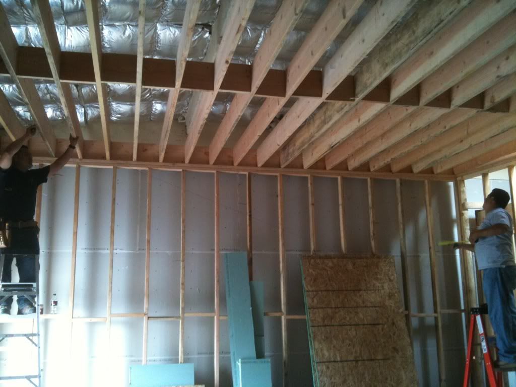
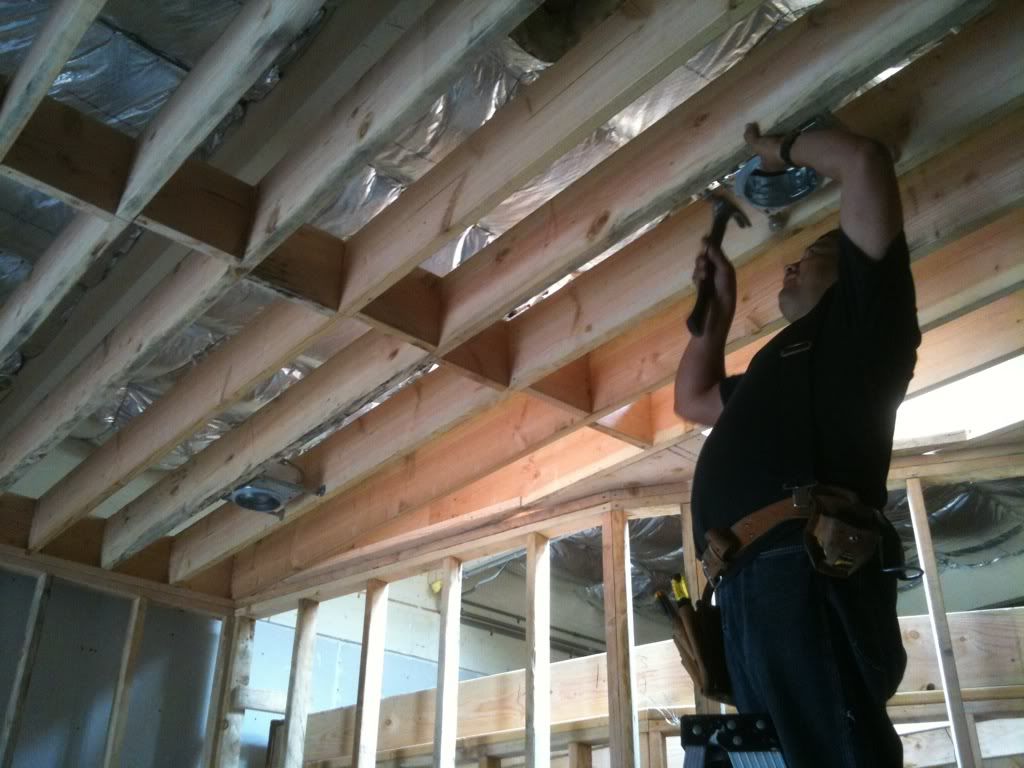
We passed the framing inspection and were given the go ahead to start electrical.
Image
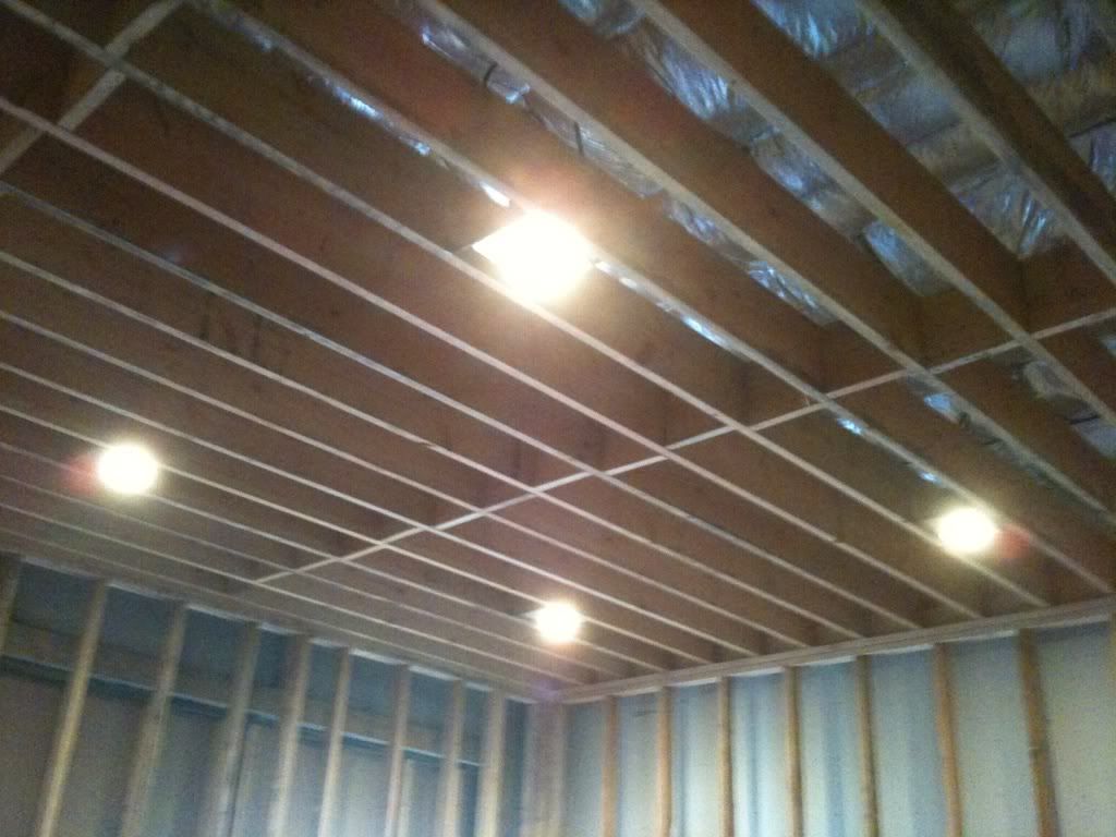
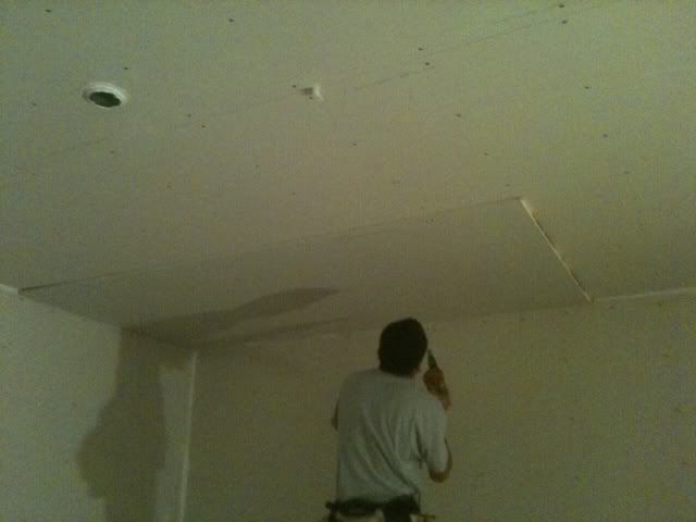
Here is a shot of my electrician chalking out where he will put the can lights for the live room ceiling.
Image
Image
Image
Image
ricotrex
Posts: 62
Joined: Tue Oct 12, 2010 3:58 pm
Location: Los Angeles

Re: Echo Bar Recording Studio Build Diary

Post by ricotrex »

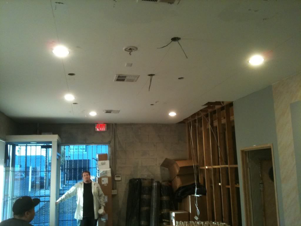
We replaced the florescent lights in the lobby/lounge/kitchen with incandescent.
Image
Image
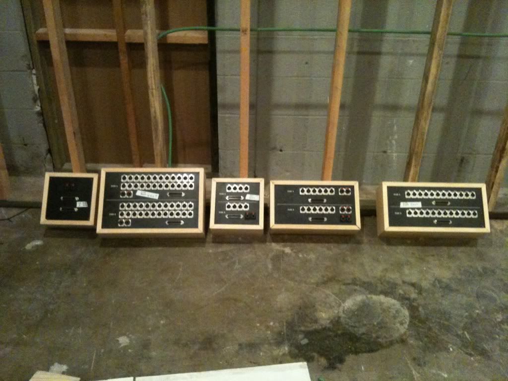
In the meantime I built my microphone panel boxes. You will notice that each panel has duplicate jacks above and below. 1 set is for my control room and the other set is for my partner's control room.
ricotrex
Posts: 62
Joined: Tue Oct 12, 2010 3:58 pm
Location: Los Angeles

Re: Echo Bar Recording Studio Build Diary

Post by ricotrex »

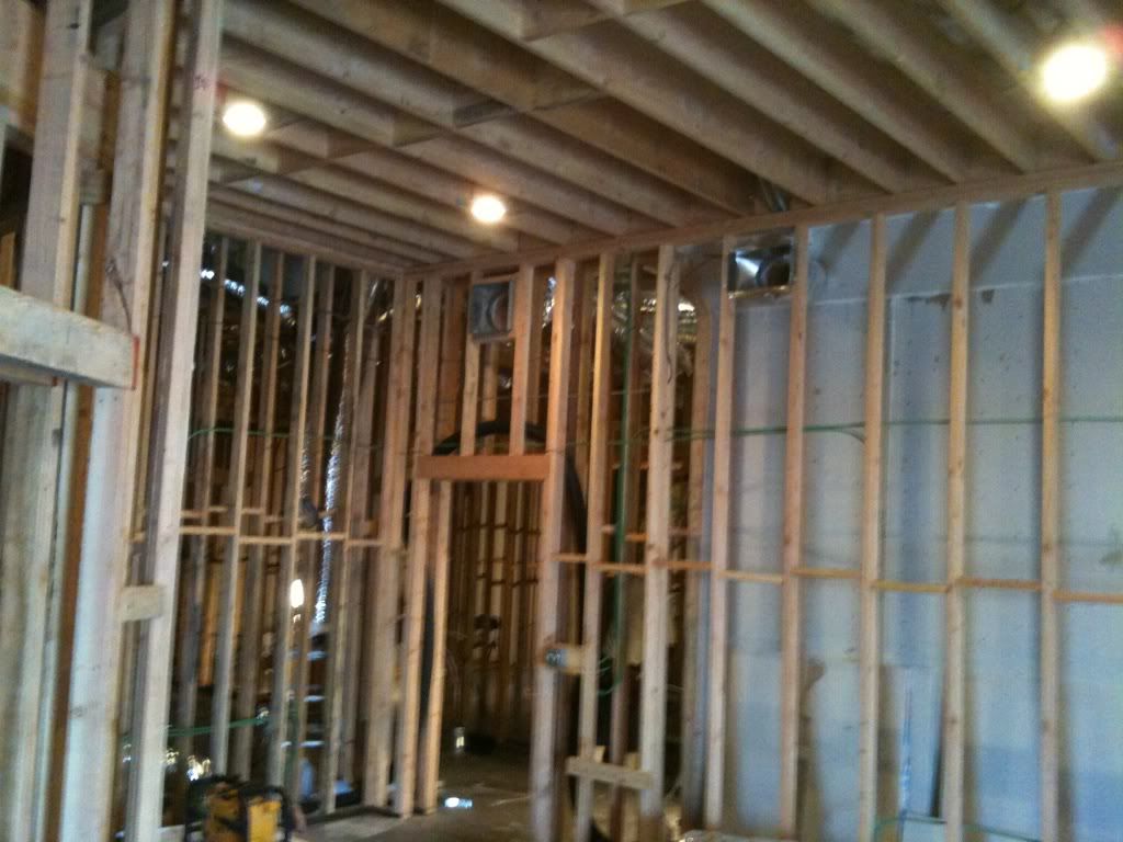
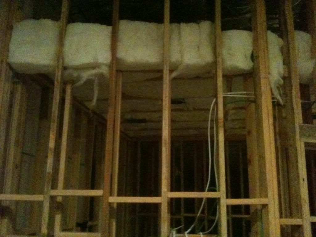
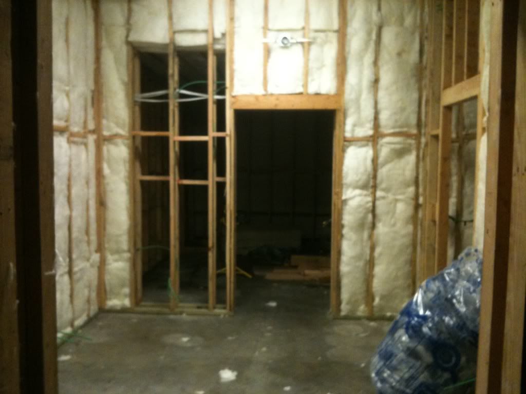
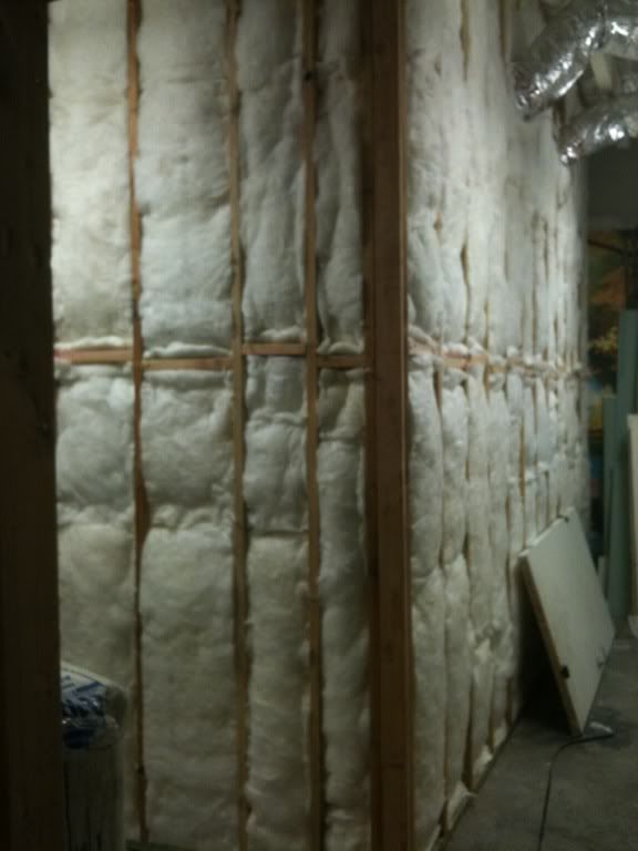
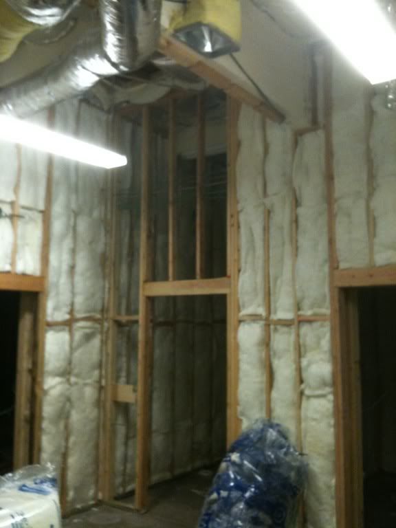
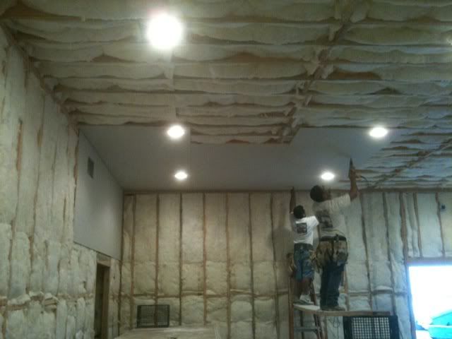
Here are shots of the insulation going in the walls.
Image
Image
Image
Image
Image
Soundman2020
Site Admin
Posts: 11938
Joined: Thu Aug 21, 2008 10:17 am
Location: Santiago, Chile
Contact:

Re: Echo Bar Recording Studio Build Diary

Post by Soundman2020 »

Nice mic panels! :)

Looking at the lighting you did for the control room, I'm wondering how you isolated those cans after you cut the big hole in the ceiling? Did you build boxes around them from above? Not clear from the photos.


- Stuart -
ricotrex
Posts: 62
Joined: Tue Oct 12, 2010 3:58 pm
Location: Los Angeles

Re: Echo Bar Recording Studio Build Diary

Post by ricotrex »

Sorry I've taken a while to up date this. I've been very busy actually doing sessions in the new studio.
ricotrex
Posts: 62
Joined: Tue Oct 12, 2010 3:58 pm
Location: Los Angeles

Re: Echo Bar Recording Studio Build Diary

Post by ricotrex »

Image
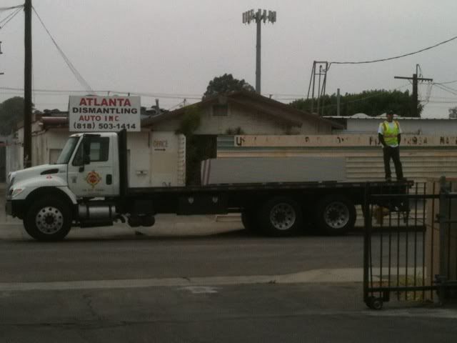
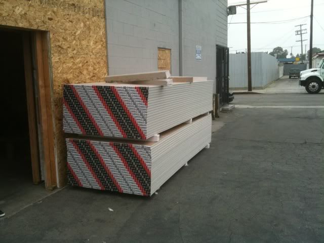
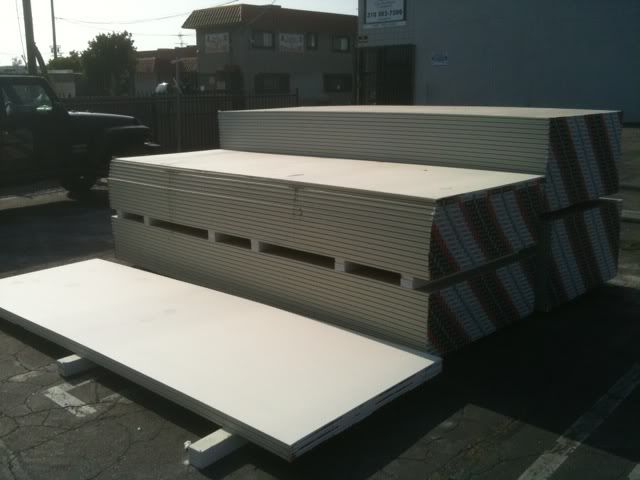
Here is the first of the Drywall being delivered.
Image
Image
And More Drywall. We used 5/8" thick type X Drywall.
ricotrex
Posts: 62
Joined: Tue Oct 12, 2010 3:58 pm
Location: Los Angeles

Re: Echo Bar Recording Studio Build Diary

Post by ricotrex »

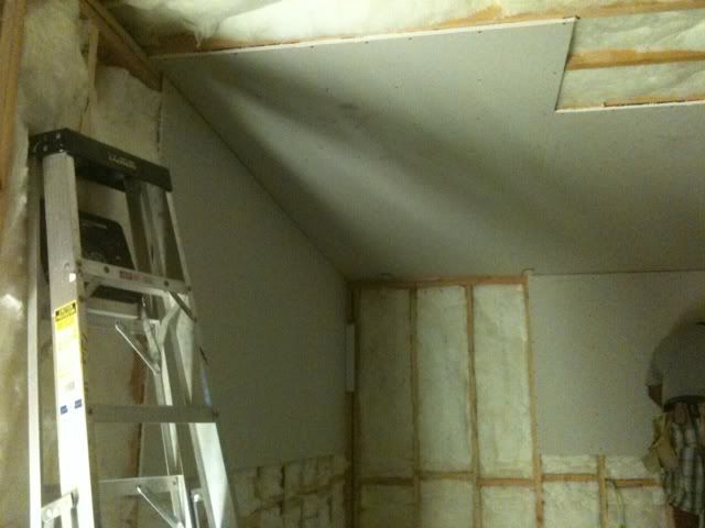
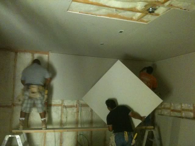
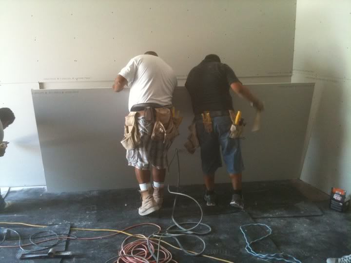
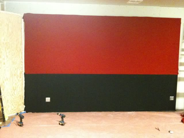
Here is some of the first layers of drywall going up.
Image
Image
Image
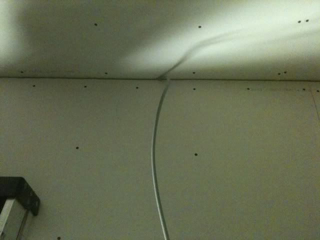
We used backer rod and OSC 175 Acoustic caulk in all the seams to make things air tight.
ricotrex
Posts: 62
Joined: Tue Oct 12, 2010 3:58 pm
Location: Los Angeles

Re: Echo Bar Recording Studio Build Diary

Post by ricotrex »

1st layer of drywall in live room going up.
Image
ricotrex
Posts: 62
Joined: Tue Oct 12, 2010 3:58 pm
Location: Los Angeles

Re: Echo Bar Recording Studio Build Diary

Post by ricotrex »

Image
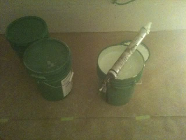
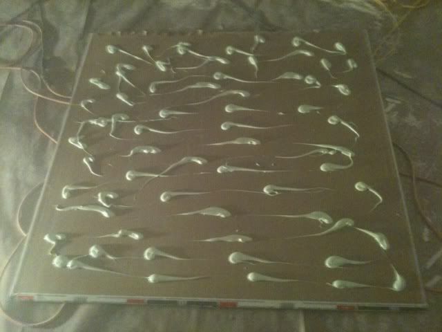
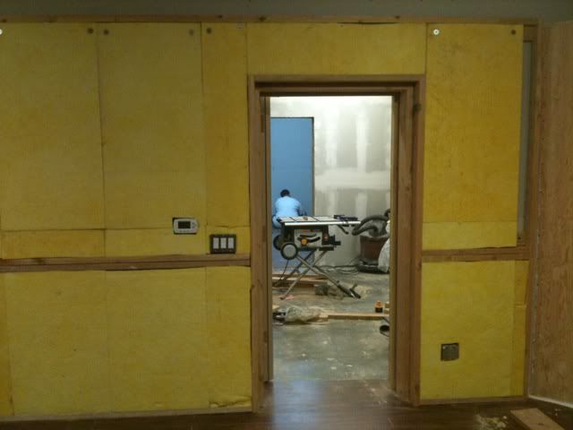
We used green glue in-between the 1st and 2nd layers of drywall.
Image
ricotrex
Posts: 62
Joined: Tue Oct 12, 2010 3:58 pm
Location: Los Angeles

Re: Echo Bar Recording Studio Build Diary

Post by ricotrex »

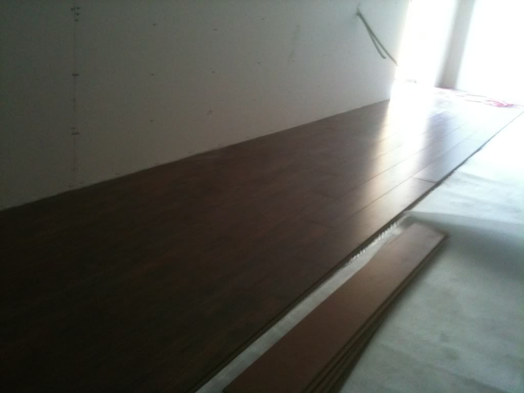
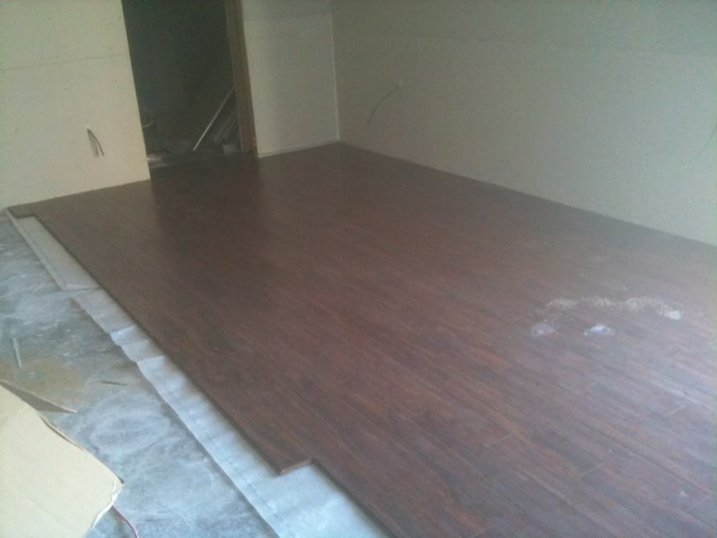
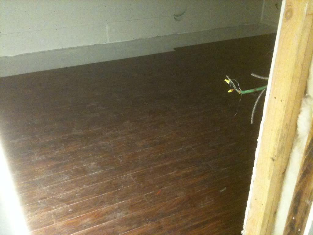
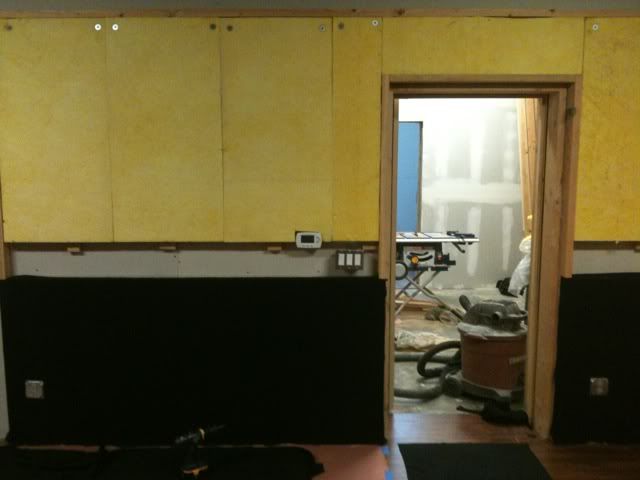
Its also worth noting that in-between the 1st and 2nd layer of drywall I layed down the hardwood floor. This allowed for a better seal between the 1st and 2nd layers of drywall. I used backer rod and caulk again.
Image
Image
Above, these photos are of the live room floor going in.
Image
Above this is my control room floor going in.

2nd layer of drywall going up.
Image
Image
ricotrex
Posts: 62
Joined: Tue Oct 12, 2010 3:58 pm
Location: Los Angeles

Re: Echo Bar Recording Studio Build Diary

Post by ricotrex »

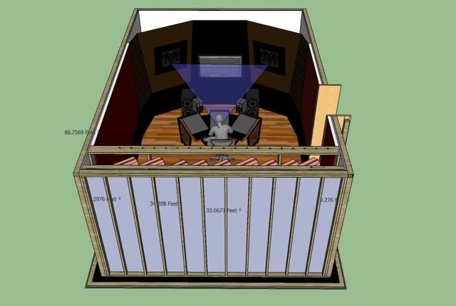
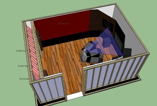
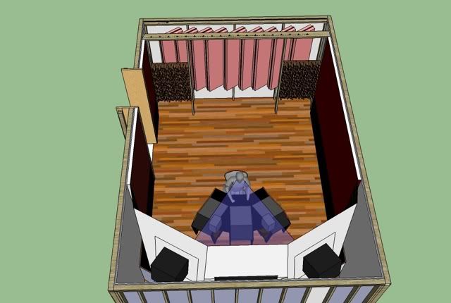
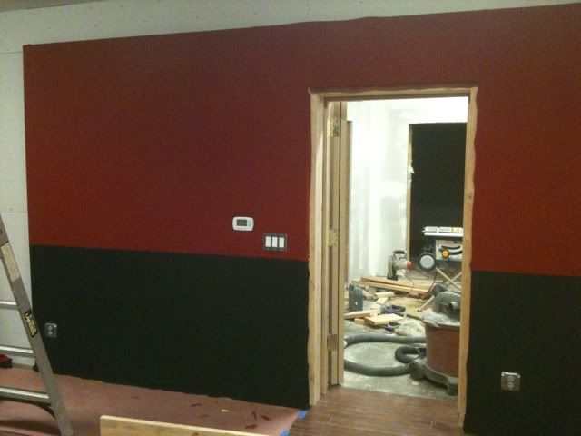
The next set of photos are of my Control Room. These will show how I chose to treat my room acoustically. I spent a lot of time planning my room design. Somewhere on this forum someone stated that, "You should design your room around your speakers." Or something very similar to this. My apologies for not remembering who said this. And my apologies for not quoting you exact. But, I really connected with this statement. I bought my speakers well before I designed my room. My main speakers are Dynaudio Air 25's with 2 x Air Base 24's. I also have a near field pair of Dynaudio BM5a's. So, I designed my room with these speakers in mind.
Image

Image

Image

As I stated earlier in this journal my control room dimensions are based on the Sepmeyer ratio. A couple of details you will note are that I chose to soffit mount my speakers. I also chose to angle them in 60 deg and down at 10 deg. The speakers' height is specific to my body height and where I wanted the listening position to be in the room. These angles and speaker height allow my listening position to be within the 38% rule in my room which has a length of 21', width of 14' 4", and a ceiling height of 9'.
ricotrex
Posts: 62
Joined: Tue Oct 12, 2010 3:58 pm
Location: Los Angeles

Re: Echo Bar Recording Studio Build Diary

Post by ricotrex »

These next photos are of the side wall and back wall construction of my Control Room.
Image

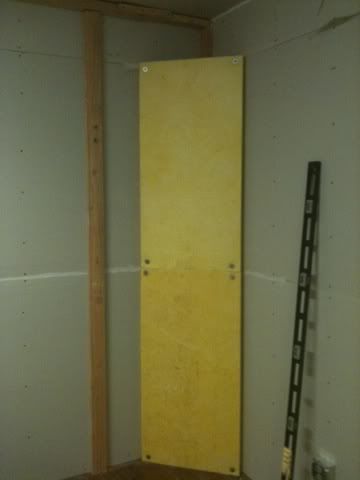
This is the start of the back right base trap in my back wall of my control room. This is a modified design based on Ethan Winer's sealed panel traps. This photo is of a 2 pieces of 2 inch thick rigid fiberglass straddling the right corner of my back wall. What is not clear in the photo is how I attached it to the wall. What I did was to rip a 2x4 at a 45 degree angle down the length of the board. I bolted these two haves to the drywall thus making a frame to screw the insulation to. I used fender washer to keep the screws from pulling through insulation.

Image

Then I ripped another 2x4 and screwed them to either side of the insulation and made a new frame to attach the wood panel to. This I glued with wood glue and sealed with acoustic caulk around the perimeter of the 2x4's and the drywall. I cut a triangular top cap to place on top of the trap which I glued and screwed into place. The idea behind these traps is to make sure they are sealed air tight. You can see the caulk in the photos.

Image
ricotrex
Posts: 62
Joined: Tue Oct 12, 2010 3:58 pm
Location: Los Angeles

Re: Echo Bar Recording Studio Build Diary

Post by ricotrex »

This next photo is of the the side wall of my control room. It shows the frame work I built for the insulation and fabric cover.


Image

This framework allowed me to leave an air gap between the insulation and the drywall. The insulation is once again 2" thick.

Image

Image

Here is a photo of the opposite side wall and the entrance into the control room.

Image

Image

Image

Image

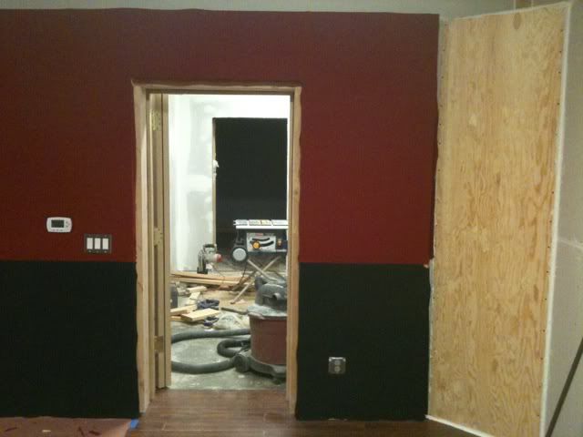
It should also be noted that I had my electrician surface mount all electrical outlets and light switches. This prevented any major holes made in the drywall.
ricotrex
Posts: 62
Joined: Tue Oct 12, 2010 3:58 pm
Location: Los Angeles

Re: Echo Bar Recording Studio Build Diary

Post by ricotrex »

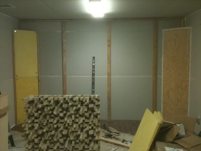
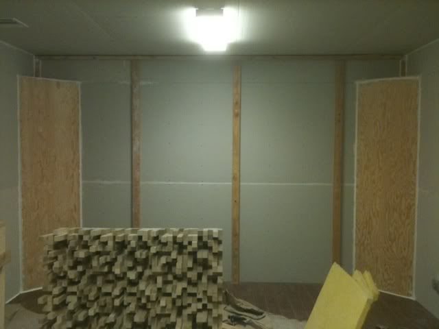
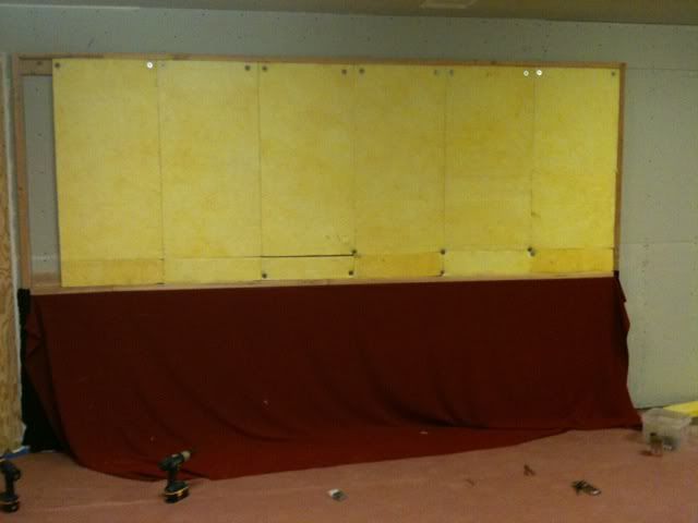
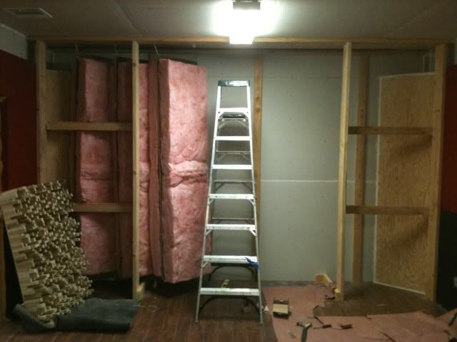
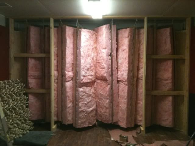
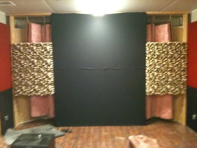
These next photos are of the continuing construction and treatment of the Back wall of my control room. In addition to my corner panel traps I also added "hanger" base traps as described by John here on the forum. They are made by sandwiching a piece of sound board i.e. (homosote) between two pieces of fluffy fiberglass insulation. They are then hung from a frame work and thus suspended off the floor.

Image

Image

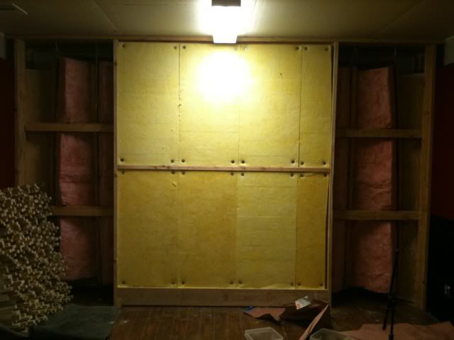
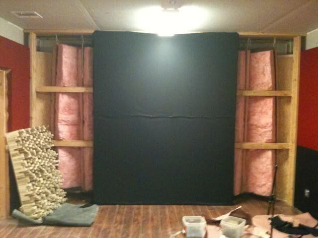
In the middle of my back wall I chose to put more absorption.

Image
Image

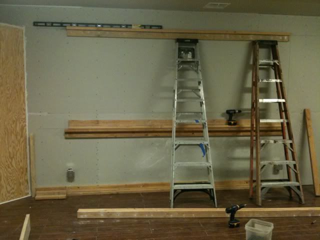
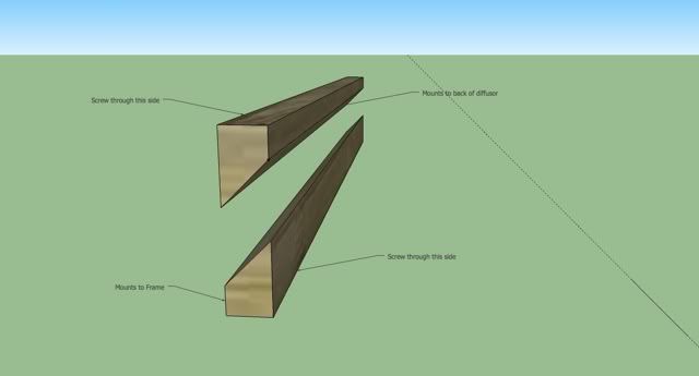
What you can also see in these last photos are the mounts for the diffusors I built. They are "french cleats". It was the best way that I could figure out to mount both of the extremely heavy diffusors on to my back wall frame work.

here is a detailed design of the french cleat method I used.

Image

This was exciting to finally mount these diffusors onto the wall. Sorry for the blurry Photo. There are better photos later on.
I should also mention that I mounted these at a specific height to the advantage of where my tweeter and mid range driver of my Air 25's are aimed in my room.

Image
Soundman2020
Site Admin
Posts: 11938
Joined: Thu Aug 21, 2008 10:17 am
Location: Santiago, Chile
Contact:

Re: Echo Bar Recording Studio Build Diary

Post by Soundman2020 »

"You should design your room around your speakers." Or something very similar to this. My apologies for not remembering who said this.
I think that was me! At least, that's my philosophy, but I bet I'm not the first person to say it, so I can't claim copyright! :)

Anyway, a few comments on things I noticed in your photos:
This is the start of the back right base trap in my back wall of my control room. This is a modified design based on Ethan Winer's sealed panel traps.
Panel traps have to be sealed, yes, but I don't understand how yours will work, since they seem to be angled across the corner, and therefore the cavity depth is not constant: So how is that going to work? What frequency did you tune them to? I'm not aware of any theoretical basis for how such a trap would work, or how you would go about tuning it, so I'm intrigued about how you did that! Maybe you could explain?
In addition to my corner panel traps I also added "hanger" base traps as described by John here on the forum.
Hangers are great, but yours seem to be touching each other, so they won't be working too well either. You might want to try strapping thin insulation closer to the board, so that they don't touch each other. Maybe wrap them with wire, or some such. Unless the hangers are able to swing freely, with air gaps between them, then they'll just act like expensive absorbers, not like hangers. You also should put some absorption on the rear wall, behind the hangers. That's part of the system.
This was exciting to finally mount these diffusors onto the wall.
Are those N7 QRD's? Looks like they might be. What is the low frequency cutoff for those? Looks like they go down fairly low.

Also, you never did answer my question from back in November, about how you isolated the light cans after you cut the big holes in the ceiling drywall.


- Stuart -
Post Reply