And, sorry Jeff, but you didn't really help to prevent it from happening.
I believe that.
[list]I made a point.
I substantiated my point with measurements specific executed for this purpose.
Either I falsified my measurement data or I proved my point.
It's as simple as that.
Personally, I don't think you falsified anything. I think you made your point(s) just fine. But I don't think it was enough. I might appear to be in the "doubting Thomas" camp when I type this, but what about testing the same samples in the same configurations without the edge screening. Was that done? All you've shown (referring to graph in previous locked thread) is that there is more than just edge effect going on.
Of course, that should be ample proof to Ethan that there is WAY more going on than edge effect. But it doesn't prove that there is no edge effect.
The stupid situation occurs, that first my measurement's quality and validity are questioned (which I take personally since that goes directly to my integrity and that of the Prof. involved), then more extensive prove is demanded from me, as arguments to hide behind by a writer, who wrote an expert article and (mis)uses its related conclusions, with an extreme penetration to countless readers, based on nothing.
I demand nothing from you, Eric. I believe your data to be useful and completely trustworthy - as is the source! :):):) I just don't think that we can discount the effect of exposed edges from the results of those two tests. Please let me know if I missed something.
And you hardly can distinguish those points as individual autonomic events as Jeff entered his quote. Hence this is only diversion within the context of this thread.
I don't think there is enough information out there on this topic to be able to conclude that.
Even top acousticians don't agree on all points in function of exact modeling, and it's a typical topic which at one point or another is studied in about any lab.
One thing they all agree on that it is NOT what Ethan says.
Not one related prediction algorithm I know off, handling this edge effect, takes edge surface into account, which while for Ethan unacceptable and incomprehensible, for me looks as normal logic. One wants to find the expansion outside the board of this area of influence, therefore one needs to know the edge length versus the surface (hence, as a poetic license one could call it a shape factor to rate how much edge is involved versus covered area). Better algorithms also try to cover for overlapping influences at different distances. They try to define limits of influence in function of frequency (wave length).
All extremely good points.
And this IS IMPORTANT to feel, even when not able to quantify it.
If I take 50% ceiling tiles away, then Ethan's approach masks that I will still keep 80% total absorption by this phenomenon, not explained by the edge surface which is even masked by the profile system.
This is a very good point. I bears repeating and emphasis:
Eric Desart wrote:
And this IS IMPORTANT to feel, even when not able to quantify it.
If I take 50% ceiling tiles away, then Ethan's approach masks that I will still keep 80% total absorption by this phenomenon, not explained by the edge surface which is even masked by the profile system.
PS the most recent ISO standard will count the edge surface, not as a solution for the edge effect, but to make measurement results more serious if suppliers decide not to skirt the edges (bit complicated and not clear yet for all circumstances). In the US it seems that skirting is almost a sin and their it's more important due to smaller sample sizes.
Applying this should alter a LOT of published measurements in negative sense currently available on the net, including RealTraps ..... (I still need more study work to see the exact consequences, for not clear covered circumstances)
This is good news. If the ASTM can follow suit, then we can all stop worrying about this! :D
Ethan,
I hope you are going to address all the concerns from my "dissertation" on THE NUMBERS GAME. Going back, I see that you've failed to answer some of the questions. And/or, it appears that you've ignored some of the points that were made. (Instead focusing on things like capitalization.)
No worries if you'd rather not. Just thought I'd mention.
And I believe Eric did at least show that there is WAY more going on than edge effect. That along with the other research we've cited for you (you're welcome...again...) should help you put a better explanation together for your customers.
Hopefully,
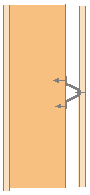
In the appplication where you used RC you were dealing with a 2" x 4" stud frame freestanding and 4" off the outer wall if the report is correct. As I said before the idea of RC is to lift the drywall off the stud to decrease sound transfer into the stud and hence through to the next drywall layer.
Recovered from web.archive.org — originally hosted at http://www.saecollege.de/reference_material/images/Wall%2012.gifIn the case of the drum room adding the RC would have increased (raised) the resonance as drywall on RC is not as rigidly attached (braced) as drywall directly attached (glued) to a stud wall, even more so when the stud wall is further strengthened with horizontal stringers at 4' spacing (a system that incidently is compuslory in my country in all stud wall constructions but is apparently is not in the US).
cheers
john
I'll be happy to look into this in more detail for you. I would like to be sure (100%) that we're talking about the same thing. Your illustration showed what we call "hat channel." Resilient channel is not the same thing - it only has a single mounting flange. I'm looking into it anyway, but I thought I'd mention this since it wouldn't be the first time it was confused. :D
Jeff thanks,
I didn't refer to you in function of questioning my data (previous thread mainly). (you know that)
About this seperation, last thing:
I do have indirect related measurements, but I'm not going to enter them, because they are not used to learn but to search how they can be questioned and which ones people want more, and secondly I'm not Santa Claus as well. These data are an asset for me.
But I measured baffels (upright standing) with perforated versus non-perforated frames.
I tested in other sessions perforations seperately (lots of types) so I knew those frames were acoustic transparant.
Summarized: I do know the difference between reflective and non-reflective edges. And what happens is EXACTLY what one theoretically can expect in function of standard acoustics.
Were the wave length becomes relative small or in the neighborhood versus this closed edge one gets reflection which translates in somewhat (gradually) lower absorption for those high frequencies.
Which is why I referred in this thread to ray acoustics....
And basically there is some analogy with the wavelength related to the diffusion/reflection of slat Helmholtz resonators.
This overall effect however as baffel use is that small, that in projects I mainly used the principle when it could give some psychological advantage, sometimes even on request of a customer for that purpose.
I made such things with thousands (and that's NOT a matter of speech), hence this perforation did cost me very little.
Still for most projects it wasn't worth bothering. In the mids or lows it didn't do a thing or it was almost within measurement uncertainties.
And very clear: there is nothing linear about the effect of a closed versus acoustic transparent frame. There just happens what logic tells should happen.
I measured it only for free upright standing absorbers.
And also don't forget that a closed frame also will react as a reflective boundary from the inside as well. How to model all this?
I've wondered a lot about that. skirting samples not only screens the path but also creates additional reflective boundaries. How to isolate those effects from one another?
Jeff,
I agree with John - this has become pathetic, and it's a huge waste of time for all of us. Maybe you have nothing better to do than nit-pick to death how I capitalize Sabins, but I have much better things to do than defend myself against this silliness. If you enjoy being known as one of the guys who harasses Ethan all over the 'net for no good reason other than loyalty to your former employer, be my guest. Frankly I'm sick of it, and I can't imagine anyone reading will conclude my failure to provide yet another blow by blow rebuttal is an admission of any sort.
I stand by everything written on my web sites. But as soon as someone provides compelling evidence of an error I'll gladly make the change, as I did with ASTM and Sabins. If Eric wants me to believe that edge diffraction accounts for more of an increase than exposed edge surface, he needs to do a lot better than what he's shown so far.
As for your frequent admonition to lighten up, I suggest you look in a mirror pal. Okay? Thanks. :roll:
--Ethan
Ethan,
I admit you're incredible ........
I couldn't make things any clearer than you did now, in relation to the context of this (and previous) thread.
I leave you and this thread now with a reminder of the quote of your friend Terry Monthy, you even worked together with as recent as Oct 2005:
http://www.realtraps.com/eq-traps.htm
And you can hardly state him as one of the guys harassing you, and by you yourself referred to as acoustics expert.
<snip> Many of us on the forum with better science backgrounds have tried to teach him things in the past, with only very limited success. We tend to get frustrated, and have largely given up trying. When he posts incorrect information as acoustical fact, it is pretty much useless to argue, at least on the basis of science.
I like Ethan. He is a nice guy. <snip>
Even the blind should start seeing now.
At least I'm sure that some learned a bit from this
Ethan Winer wrote:
bitter little man who has nothing of substance to offer
and will remember.
Ethan Winer:
What you do is misleading ten to hundred thousands of people just to serve your stubborn non-educated ego and commercial interests at the expense of others, without any sense of responsibility or shame. People rely on what you write.
The word diffraction (just a word for you) you started using after the previous SOS thread, where the same was discussed with as little effect (as so many times before about this and lots of other topics, which are of real importance for your readers).
AGAIN you turn the world upside down. YOU are responsible for what you write. That should not depend on others.
A thread like this shows how you handle such responsibilities.
And people can also understand "how" to read things you write, and see the attitude behind this, which also reflects in other things you write as e.g. your utterly disrespect for standards in your wittingly wrong representation of data.
This thread was a follow up and related to:
http://www.johnlsayers.com/phpBB2/viewtopic.php?t=6369
I agree with John - this has become pathetic, and it's a huge waste of time for all of us. Maybe you have nothing better to do than nit-pick to death how I capitalize Sabins, but I have much better things to do than defend myself against this silliness. If you enjoy being known as one of the guys who harasses Ethan all over the 'net for no good reason other than loyalty to your former employer, be my guest. Frankly I'm sick of it, and I can't imagine anyone reading will conclude my failure to provide yet another blow by blow rebuttal is an admission of any sort.
I agree with John, too, but not for the same reasons. I sure don't like being insulted over and over. (Four or five times in that paragraph alone, I see.)
My loyalty, btw, is to the science of acoustics and better sound for all. You are the one fabricating the allusions to my former employer.
I stand by everything written on my web sites. But as soon as someone provides compelling evidence of an error I'll gladly make the change, as I did with ASTM and Sabins.
I'm sorry - very sorry - but I cannot believe that. You have been given evidence time and time again, over and over, ad infinitum. And you continually choose to ignore it. You have not changed the references to absorption coefficients and percentages even though I can name - and have cited elsewhere - numerous relevant references. You have not removed the calculations of absorption coefficients from J-mounting tests even though it's been pointed out to you numerous times that they're not allowed per the testing standard. And so on...
I will say again - I'm just trying to help. :?
As for your frequent admonition to lighten up, I suggest you look in a mirror pal. Okay? Thanks. :roll:
If the furring supporting the gypsum board (away from a masonry wall) is rigid, sound can travel directly through it from the gypsum board to the blocks. However, if the furring is sufficiently flexible, the sound will be attenuated. But the best method of support for the gypsum board is the use of independent studs that have no direct connection to the block. Resilient metal furring may be used on its own or in combination with wood furring.
Is my interpretation bad? I realize this is mostly talking about furring that's attached to the masonry, but I don't believe the concepts would be that much different for detached furring (studs). I cannot picture a situation where the resonance would get worse, as you suggested. I think it would be different, but not worse...
I dug pretty deep looking for supporting test data - couldn't find any. But - again - I go back to my gut. My gut tells me that the application in question is perfectly acceptable. And the above paragraph from the gurus at NRC-CNRC sets my mind at ease a little.
Thoughts?
Jeff - I think we are confused here ;)
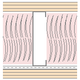
I've attached a drawing showing two mountings using RC. The one on the left is what they are referring to in the use of RC and block walls. The one on the right is what I understood was advised in the drum room construction.
In the second one the RC is unnecessary as the stud wall detaches the drywall from the brick wall.
cheers
john
Jeff - I think we are confused here ;)
I've attached a drawing showing two mountings using RC. The one on the left is what they are referring to in the use of RC and block walls. The one on the right is what I understood was advised in the drum room construction.
In the second one the RC is unnecessary as the stud wall detaches the drywall from the brick wall.
cheers
john
Again, your drawings show hat channel - but I'll give you the benefit of the doubt here.
I do understand what you're getting at, but I disagree. The drum room TL (mostly high frequency range) and room acoustics (low frequency range) both benefitted from the RC. I don't think the changes in resonance would negate the need for more TL. I certainly think a more resilient inner layer can help small drum rooms in certain instances, this having been one of them.
(You might also note that I did not write the blurb on the web.)
Jeff, that's not necessarily hat channel; Dietrich make both single and double legged resilient channel, and don't recommend either of their single legged stuff for ceilings. Same cross-section as hat channel, but has lotta slots in BOTH of the angled sections... Steve
Sorry Jeff - it was a quick drawing and possibly intercountry terminology.
here is what I'm referring to.
http://www.pac-intl.com/assy_dwgs_wl_wood.html
Not one of the assemblies proposed using RC with a single layer as you proposed in that drum room.
You all should also note that according to this company the highest STC of 66 is obtained using a 4 x leaf construction!!
cheers
john
STC, maybe; but I bet the bottom end isn't worth crap... Steve
actually - I couldn't figure out how you'd build it!! But it was 3db better than two sheets aside a single wall and they did recommend it for walls between apartments, if you could build it , that is.
I assume they've done the appropriate tests.
maybe the graphic should be this one.
cheers
john
John, you are correct, the RSIC rubber isolator does react very differently than the old standard method of mass air mass.
The acoustical results on this are based on two STC 56 wall systems.
We only attributed 10 STC pts to the 2nd wall system.
The advantage of having the RSIC-1 clips on the interior of the dbl wall is that you can mount pictures or shelving to the wall directly to the studs. Our original design had the RSIC clips on the outside layer of gypsum board to help reduce the possible flanking paths.
The real test will be the low frequencies. Our current focus is general construction, Condos, apartments, time share, hotels, and resorts. Unfortunately the only worry when dealing with this group of builders, is the measured STC, not the exact performance at each frequency. With that being said, this is a wall type that we probably will not run out and test at Riverbank. Our current focus is getting rid of the dbl wall in apartment construction, and getting the builders back to simple systems that work.
Construction would have to be while the framing is laying flat on the ground, athen tilted into place. Once in place the perimiter needs to be caulked. When that is done you can insulate, then install the finish layer of gypsum board.
Please call or email if you have any additional questions.
Mike Gernhart
[removed]
[removed]
John,
I guess now I'm really confused. :?
Are you saying the RC im that drum room was unnecessary because the company that makes an alternative to RC said so? (Sorry - couldn't resist. :oops: )
I agree that the link you provided shows some darn good construction details. Good company, good products, good methods, etc.
But I don't think that it has much to do with the specific RC/drum room questions you originally had. Could an alternative construction using RSICs have been implemented in that room? Probably. I agree with Steve that the low end in the room probably wouldn't have been as good. But, overall, I am sure there are probably several other approaches that could have been considered and implemented successfully for that particular drum room.
Anyway, I appreciate the dialog! 8)
Yes Jeff - I'm saying it was unnecessary because of the type of construction. Had the construction used the original outer brick wall as it's inside wall then, yes, RC mounted on the brick wall would have been useful, but seeing as a new stud wall was built internally the RC becomes unnecessary.
Yes Eric - it appears they have made a few assumptions on this particular wall construction. You must admit their other test results and construction diagrams are very helpful. I fully understand what Mike means when he mentions double wall construction in condos and apartments and I also understand the problem of hanging shelving and pictures on RC suspended walls.
The closest figure I have is for a triple layer with one layer on RC which is STC64
Recovered from web.archive.org — originally hosted at http://www.saecollege.de/reference_material/images/Wall%208.gif
I've invited Mike to reply via this thread should he wish to join us.
cheers
john
Eric,
So you are saying that the edges have nothing to do with increasing the absorption coefficient number when the edges are open?
thanks,
Glenn
No I'm not saying that, nor did I said that anywhere in the thread.
Translated by Cadesignr: I admitted that edges absorb.
Where absorption material is absorption can occur as 1 + 1 = 2 (but that must be seen within the correct acoustic context), not as: Hé guys, another 1.5 feet to add.
I referred, in relation to Jeff's message that all those phenomena are difficult to distinguish. All, or lot of those things interact.
And I told that my perforated baffles give somewhat higher absorption, but frequency dependent.
I referred to ray acoustics for that part.
Glenn, what I said is in the thread.
If you want a simple rule for a complex phenomenon I can't give you that.
But approximation models to calculate such things do exist. Several authors are referred to. But still then it remains a difficult thing.
Your Tri-corners will show edge effect absorption on those sharp edges as well as on the junction wool/closed top.
This thread was/is about the relationship of, and resulting calculation by EW, in function of a OVER simplified incorrect frequency independent linear relation between edge effect and geometric edge surface, and that's wrong.
Some will know this document:
Please take the time to get the feel:
This was on the net since 2000 or 2001 about.
http://filexoom.com/files/5434/Acoustic ... rption.doc
Ethan Winer knows this doc very well, since it was actively discussed at Yahoo Acoustics (predecessor Studiotips) more specific in function of the high efficiency of corner absorption. (note that this are framed absorbers).
Important in this document:
In fact one can analyze a lot of things from that document.
In this document, also the 2, in this thread questioned measurements are included.
Important in function of Glenn's question and Cadesignr's comment.
When an absorber is measured upstanding, then both sides are 100% exposed to free sound incidence (expressed in the terms used here, personally I do have question marks with this expression, a panel against a wall for me is as well 2 sided exposed).
Cadesignr: :oops: I very humbly admit that both exposed sides of these absorbers absorb.
I can hardly say they don't. I should be stupid.
But what does that mean?: without putting it in the correct acoustic context: JUST NOTHING.
If you compare the mid and high frequencies on those graphs in this document you'll notice that the absorbers flat on the floor, with only 50 % exposed area to the room versus to the upstanding ones at 100% is roughly comparable.
And the thickness of those absorbers is +/- 6", hence thick enough not to question complicated things in the high frequencies with short wavelengths.
Hence: this so-called both-sided free exposed absorber surface does not translate in even remotely comparable increase in absorption. Those values even remain close together (hardly word bothering to check which curve is which, while the visibly exposed surface is DOUBLE versus one another).
Now you can compare screened upright absorbers versus not screened upright absorbers. The comparison isn't completely correct here.
I just use what I put before on the net already.
Such measurements are executed to study the phenomenon of screening as well as the effect of the measurement method in itself.
The measurements which should be OK for publishing as per official standard are the screened ones, not the free ones.
This screening is 35.4" = ca 3' high. This height influences the room already, but still this are DIFFUSE FIELDS. That sound comes from anywhere.
This edge surface (I know this is a limp comparison) is 1.5 times the enclosed area. As per the Ethan Winer reasoning the absorption should increase up to a total of 250% (100% + 150%) versus the screened ones. Check for yourself.
Glenn, I did not say they those edges have no effect with or without frame. Absorption will have. This DOES NOT MEAN THAT YOU JUST CAN PUT AN OVERSIMPLIFIED INCORRECT ALTERNATIVE INSTEAD, as this document shows.
Cultures tried to find things they could give a place in their live for phenomena they didn't understand. Hence they worshipped the sun as a god. You just don't give an explanation because you don't understand something.
I'm busy with this stuff for close to 30 years.
Well I can not compress acoustics in some simple rules of thumbs. And I still wonder about lots of things. And the more I learn, the more I wonder.
While only 13 measurements are shown in this doc. This session included over 50 measurements.
+++++++++++++++++++++++++++++++++++++++++++++++
Some dry facts about corner absorption and the info on the net.
A minor bit of the history is noted in the document linked above.
Unlike Ethan Winer claims Ethan saw the first framed corner absorbers in this very corner absorber.doc, and learned about corner absorption at Yahoo Acoustics the predecessor of Studiotips.
The post is still present where Ethan disputes the value of a fiberglass panel straddling the corner with Scott Foster in favor of his panel traps, which was the product RealTraps was originally established for.
As far as I could find the Acoustics Yahoo group were about the only one promoting this approach.
My corner absorber.doc must be the oldest and first document on the net showing a measurement and explanation about the efficiency and typical behavior of corner absorption.
While used before (limited), hardly any lab had any idea about this behavior.
Hence it's possible that John used it in the 70ties, but also in Australia a test executed within the last 2 years in an Australian lab, caused the same surprise about this typical behavior with those academics with decades experience.
The same goes for the Labs I know here, and I had contact with David Moyer from Riverbanks (the original Sabine designed lab) also confirming that only the last couple of years such measurements appear.
While Auralex had the LENRDs already, the typical corner behavior wasn't know, which shows from discussions I had with Jeff.
Even the most recent book of Dr. Peter D'Antonio and Trevor Cox, basically says that corner absorption, not based on pressure devices (membrane/panel absorbers), are inefficient devices since corners aren't the right spot for that. Within the year after the appearance of that book the RPG corner foam absorbers appear, in fact contradicting the still existing explanation in the very book with D'Antonio as well as Co-Author and owner of RPG.
Hence the simple logic between bass build up in the corner, hence it works as well for panel traps as open cell absorption isn't that evident at all. And it's still not clear how and which parameters influence this behavior exactly, but which is certainly influenced by the room itself.
Ethan first disputed the Studiotips corner absorption approach and then toke it over.
Hence he CERTAINLY has not the right of blaming other companies, who got their knowledge from exactly the same source as Ethan Winer did.
As well the effect of a cavity, as well the effect of a membrane is explained to Ethan somewhere around of after 2002 (was it 2001? I think 2002, not sure now), when he asked how to interpret absorption value in function of cavities related to absorption lists he was linked to.
This are all dry facts I can prove.
It's a nice contrast with Ethan's comments about the same.
I know a bit the history of that patent and licenses for this corner absorption.
And to be honest, unless I find other data pointing otherwise, I must smile a bit with all those groups acting if it was/is something they knew and understood al along for ages.
This knowledge and real study work has been stuck in Sweden for very long, due to internal relationships within the International Rockwool group, where Rockwool Sweden was separated from and being a competitor of their own former Mother and sister companies abroad, with a product which is more a principle than a product that can be easily protected.
Their was Swedish documentation from for use in Classroom acoustics, auditoria, music purposes and the likes, based on the low frequent qualities. I still have some of those old leaflets, but can't read them well.
As far as I know they never where translated in English, while Rockwool Sweden was very active abroad under the name Ecomax.
If so known, then why are labs all so surprised? Why should D'Antonio & Cox write what they did? One can hardly state that they don't know the studio and sound world. And questioning their knowledge should be a bit strange no? Fact: their not alone ....
The Univ lab, where I did the first measurements (somewhere end eighties ????, can't remember), who have easy access to all papers they like (literature study is standard academic procedure) have spent a significant amount of time trying to figure out this behavior, or find mathematical relationships.
Back then they stopped (more side experiments), + uncertainties caused by frequency design range of labs.
You know that thing which is so logical for Ethan, as per himself, for decades already (numerous related posts prove otherwise).
I'm open for any new info, which gives a better insight in the history of corner absorption and when it was really studied, understood (not the same as using it as a logical complement in a room).
In the following paper I describe a project I did in 1991, and where I integrated corner absorption (I did not work for that Prof., we only published together).
This relates to a TV Studio Complex. The one in the pictures is 18000 m3 = 635664 cft
http://filexoom.com/files/5434/Acoustic ... TS%20b.pdf
Best regards
Eric
PS: David it should be nice if you enter part of that patent you refer where you have it from. The color gradient (+ compression from original monster Tiff) I put in there. That comes from my Word document.
Yes Eric - it appears they have made a few assumptions on this particular wall construction. You must admit their other test results and construction diagrams are very helpful.
I 100% agree that there site and available data is VERY good and valuable.
I once downloaded all there reports.
Brian Ravnaas's comparative studies ( :) and he sleeps with drywall and everything related with it) confirm RISC superior to any type of RC, certainly when low frequencies come into the picture, which it always does in this music/audio world.
It gives a lower resonance frequency due to a significant lower spring constant (softer). And this lower resonance of course works through in the subsequent TL curve as well.
Hence my comment was really limited to what I said.
But before and even now, RC can still be valuable since cheaper I assume.
It all depends on the required specs.
It is still a common used product.
Strictly technical/acoustical: RISC is superior. (confirmed by Brian, which on top with what I thought to know is enough for me)
Edge Effect - same two words, but I think they have three definitions in this thread.
Eric Desart's definition of Edge Effect.
When Eric talks of Edge Effect, he means exclusively Edge Diffraction.
In this case the edge is a perimeter in units of feet (a length, not ft^2, not area), a precipice.
It is the line of discontinuity between two different absorptive surfaces (e.g. fiberglass and drywall)
Thus corner absorbers can have an 'edge' even though there is no surface area.
"The absorption increase is function of wavelength, absorber area, aspect ratio (not edge surface) and the real and imaginary parts of the absorber surface impedience" (by Eric from this thread. That ray edgeeffect0cr.gif)
And that separating the absorbers increases the statistical absorption coefficient, which is a function of both the surface impedance of the absorbers and the radiation impedance.
Eric offers quotes and further reading by various acousticians since Wallice Sabine, and his own laboritory measurements and results (PlayingWithBaffles.doc and CornerAbsorption.doc and 1991%20Bouwkroniek%20VTS%20b.pdf).
When a porous material is separated, such as in a checkerboard pattern, its absorbtion changes.
Usually more absorbtion in the bass, with little change in the trebble "The discontinuity in the wave field at the edge of the specimen create a diffraction effect that warps the sound field to make the specimen appear as much as a quarter-wavelength larger in each direction." (from Proceedings of Noise Con 90, David A. Nelson, P.E., INCE Bd. Cert., "Diffraction Effect" in Sound Absorption Tests: Why is the sound absorption coefficient greater than 1.00?)
In the below link, the absorbers have frames around the sides. So this boost in absorbtion, primarily in the bass, is due to edge/diffraction effects, and not due to any increase in surface area of the porous part of the absorber such as hieght of the sides. All he did was spread them out.
http://forum.studiotips.com/files/diffraction_185.gif
from: http://forum.studiotips.com/viewtopic.php?p=16607#16607
which is an example (certainly not the only example) showing how spreading out absorbers increases low frequency absorption as a function of wavelength.
Eric feels this is the dominant effect.
Ethan Winer's definition of Edge Effect
Ethan's definition of edge is entirely related to its surface area.
It is pretty much summed up by The Numbers Game which says that absorption is proportional to the exposed surface area, actually more than just proportional it is multiplicitively related (if the surface area goes up by 50%, then the sabins go up by exactly 50%).
"When an entire wall is covered with four-inch thick panels none of the edges are exposed, so the real absorption is only 2/3 what the published numbers indicate." (from The Numbers Game)
Ethan feels this is the dominant effect, and is currently unconvinced that Edge Diffraction exists at all, or that it's effect is so trivial as to be completely ignored.
Jeff D. Szymanski's (aka lovecow) definition of Edge Effect
Jeff seems to hop back and forth between the two, and/or include both of them simultaniously, depending on the post. Namely these two:
John Kopec wrote:
C. Diffraction/Bending Wave Effects: Essentially the bending wave effect, also known as diffraction effects, theory of absorption is that certain sized or shaped specimens can cause the sound waves to bend around them, turn, or bounce back and forth. The energy used up by the sound wave bending, turning or bouncing around a specimen shows up as increased absorption caused by the specimen.
D. Edge Effects: The edges of some samples are not included in the area used to calculate absorption coefficients. For example, the area used to calculate absorption coefficients on office panels is the width and height of both sides (face arras) only. Although the edges of the panels are exposed to the sound and can provide additional absorption, the edge arras is not included in the calculations. Thus, the thickness of an office panel can be a major contributor to the coefficients exceeding 1.00.
Other found definitions of Edge Effect
edge effect
Definition: Also known as diffraction effect. The apparent boost in sound absorption coefficient that comes about due to wave diffraction at the edges of the specimen. The specimen appears to be larger than its plan area by a perimeter stripe with width proportional to la?, where a? is the sound absorption coefficient that would result from testing an infinite area. The effect increases with decreasing frequency, decreasing specimen size, increasing aspect ratio, and increasing sound absorption coefficient. Although the effect is most noticeable when values exceed 1.00, most low-frequency results for highly absorptive specimens are affected to some degree.
Diffraction: A change in the direction of propagation of sound energy in the neighborhood of a boundary discontinuity, such as the edge of a reflective or absorptive surface.
For some test specimens the method reports sound absorption coefficients greater than 1.00. This seems at first counter-intuitive because it is impossible for a surface to absorb more than 100 % of the sound energy striking it. To properly interpret this result, note the units of the sound absorption coefficient: metric sabins per square meter. In cases where the absorption footprint is larger than the area of the specimen, the sound absorption coefficient is greater than 1.00. This is called the edge effect or diffraction effect because it results from wave diffraction at the edges of the specimen. The specimen appears to be larger than its plan area by a perimeter stripe with width proportional to l α where α is the sound absorption coefficient that results
from testing an infinite area. The effect increases with decreasing frequency, decreasing specimen size, increasing aspect ratio, and increasing sound absorption coefficient. Although the effect is most noticeable when values exceed 1.00, most low-frequency results for highly absorptive specimens are affected to some degree.
from "Acoustic Absorbers and Diffusers Theory, Design and Application" by Trevor J. Cox, pg 64
Although in theory the sample should be infinite, in reality the sample will be finite in extent and so edge diffraction becomes important. The diffraction from the edges at low frequencies causes the reflected wave to no longer be planar... A rough lower frequency limit is when half a wavelength fits across the smallest sample dimension.
from "Theoretical Accoustics" by Philip M Morse, pg 454 through 463
Similar diffraction effects occur when a sound wave reflects from an infinite plane wall, one half of which is rigid, the other half soft.
...
We note that when ka is very small, the pressure on the soft strip is not much different from the 2P, which would be present if the wall were all rigid; the longer wavelength cannot accomodate itself to the narrow strip; so the dip in pressure is shallow and extends well beyond the edge of the strip.
Eric has written in a few spots that there's more than just the separation as a function of wavelength going on here that's causing the increases in absorption, and that there are many other factors. As an example of some of these other influencing factors I offer this fun document, in which they used the separation (function of wavelength) and placement (at regions of increased presure by frequency) of porous absorbers to target/damp room modes: http://www.zainea.com/periodicabsorbtion.pdf
Equally fun is the list of references at the end about the many studies that have been done about the changes in absorption coefficients by spreading out absorbers, including predictably one by Walace Sabine in 1935.
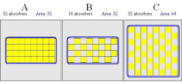
Recovered from web.archive.org — originally hosted at http://www.bobgolds.com/FloorSurfaceAreaDensity3.JPGHypothetical Lab reports that there are 25 sabins at 250hz for pattern/distribution/density A, mounted flush on the floor.
Hypothetical Lab reports that there are 15 sabins at 250hz for pattern/distribution/density B, mounted flush on the floor. (half the absorbers, plus a bit for edge effect)
Hypothetical Lab reports that there are 30 sabins at 250hz for pattern/distribution/density C, mounted flush on the floor. (same absorbers, plus a bit for edge effect)
Labs would calculate absorbtion coefficients for these absorbers divided by the blue rectangle area and mention the pattern/density and mounting:
A: 25 / 32 = 0.78
B: 15 / 32 = 0.46
C: 30 / 64 = 0.46
Studio Owner would decide if he were covering an entire wall in pattern A then he would use the 0.78 measurements as the absorbtion coefficient, but if he were covering an entire wall in pattern C then he would use the 0.46 measurements as the absorbtion coefficient. Because Studio Owner used the pattern/density that the lab tested with and the absorbtion coefficients that correspond to them, the sabins the final room will have will be pretty close to the calculation.
In the event that A were published and C were not published, an experienced accoustician might be able to kluge the absorbtion coefficients using a little math and experience into an approximate C good enough to build with.
A USA marketer would use the surface area of the yellow absorbers, rather than the blue rectangle and get
A: 25 / 32 = 0.78
B: 15 / 16 = 0.93
C: 30 / 32 = 0.93
The 0.93 looks better than the 0.46 above, and even better than the 0.78, so that's the number the marketer will put on their marketing website.
At which point, Studio Owner, unsure which pattern was used (including elevation/mounting etc), and knowing that by changing the pattern/density or mounting that the absorbtion coefficients will change, wonders what this 0.93 is. If Studio Owner assumes the 0.93 corresponds to pattern/density A, and buys/mounts absorbers according to pattern/density A, he'll end up with less absorbtion than he had calculated from.
A Studio Owner, having no other information, assumed that "standard adjacent layout" (A-ish) was followed. Alternativlely having seen a picture of the layout (C-ish) might assume that "standard hypothetical circumference (rectangle) enclosing ALL boards" (i.e. the area of the blue rectangle of C) -- in which case the 0.93 published is exactly double the 0.46 the lab calculation would have calculated to the standard, and although this Studio Owner buys/mounts absorbers according to pattern/density C, he'll still end up with less absorbtion than he had calculated from.
Knowing sabins is useless unless the pattern/density and mounting and blue area are also known.
Knowing absorbtion coefficients are useless unless the pattern/density and mounting and calculation method and data are also known.
Because you can't apply the absorbtion coefficient unless you use the same pattern/density and mounting, and know what 'area' (yellow or blue -- preferably blue) to multiply by to get sabins for your RT60 plans.
A similar analysis can be found here: http://www.acousticalsurfaces.com/artic ... rboard.htm
And of course, no big surprise, Eric wrote the same sort of thing here: http://forum.studiotips.com/viewtopic.php?p=17936#17936
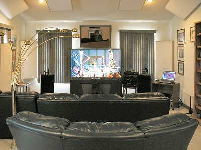
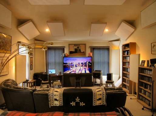
BTW, this is a great example of how to take advantage of this to maximum effect:
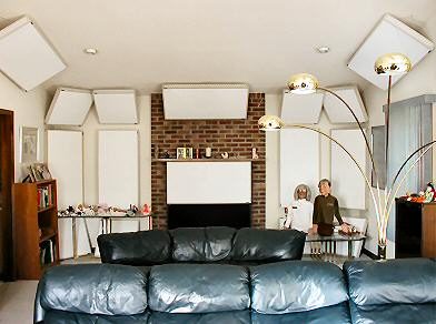
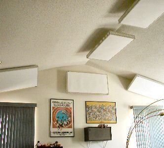
Recovered from web.archive.org — originally hosted at http://www.realtraps.com/cust_ht1.jpgRecovered from web.archive.org — originally hosted at http://www.realtraps.com/cust_ht2.jpgRecovered from web.archive.org — originally hosted at http://www.realtraps.com/cust_ht3.jpg
Equally fun is the list of references at the end about the many studies that have been done about the changes in absorption coefficients by spreading out absorbers, including predictably one by Walace Sabine in 1935.
:mrgreen::mrgreen::mrgreen:
Bob,
As usual, you are incredible (but in the positive sense) ....
Accurate and extensive.
There is a slight problem though.
Walace Sabine died in 1919 ....
Or there is another one I don't know about.
Better check this one.
Just teasing, .........
:):):)