HUB Studio

Started by Hub on 16 February 2013. 48 replies, 2013–2016. In the Library under Build diaries. Key posts in this thread.

Originally posted at johnlsayers.com, topic 18165.

We are considering the option of using the OC730 rigid 50mm thick fiberglass board on top of our existing floor followed by 2 layers of 18mm ply and then the framework on top of that.
OK, that's the "drum riser" concept, adapted to a floor. It will help to a certain extent, for sure, but won't isolate the way a properly done floor would. Still, it is certainly a good option for you guys.
Will the fiberglass compress more at the point where the inner frame of the CR & LR or will the fact that the 36mm of plywood in between will more evenly distribute the weight?
You cannot rest the walls on a floor built like that! :shock: :ahh: That would be dangerous. That method is just for the floor alone, no structure on top of it. It is not meant to be load-bearing. The walls will still have to rest on the real subfloor, not on top of that "drum riser" deck. - Stuart -
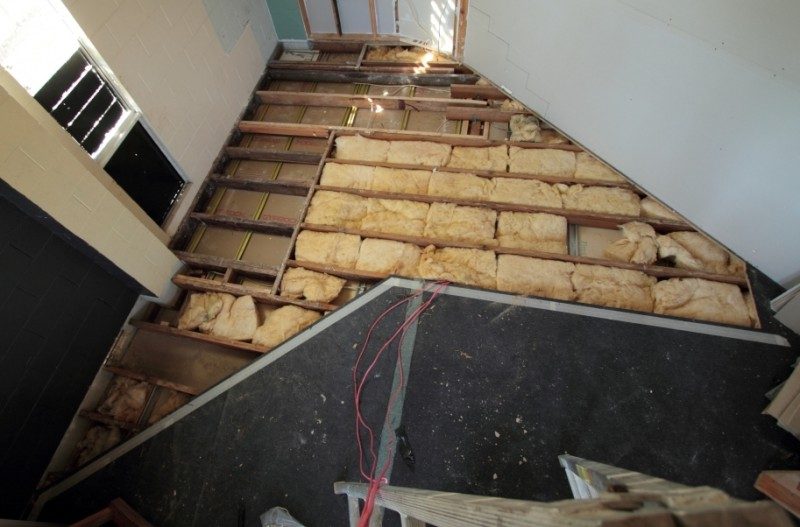
Question 1 If we were to lift the rest of the existing plywood floor (as we have done in the live room area), could we benefit from using 2 beads of neoprene sealant along the top edge of all the bearers before we put the existing floor back down and not screw this but allow the sealant to set, also use neoprene sealant between the floor and the walls so there is no mechanical connection and by this will it result in extra DE-coupling? The other way we could do this is by using the neoprene striping which comes in 10m rolls at 50mm wide x 3mm thick and glue this down to the bearers before we put the floor back on.
LR 1.JPG
LR 1.JPG
Image not preserved: LR 2.JPG
Question 2 If we use the OC730 rigid 50mm thick fiberglass on top of the existing plywood floor then we add the 2 x layers of 18mm plywood on top of that(stagger the layers, glue together and screw only the 2 layers together with screws spaced at 300 centers) do we then cut the floor about 5mm from the CR & LR finished internal walls and fill the gap with neoprene sealant(as was mentioned before)? Question 3 When we put the CR & LR frames on top of the existing floor do we also place some neoprene underneath this, say either pads or we can get 75mm wide x 3mm thick under this? The sizes the strips come in are 50mm wide x - 1.5mm thick - 3.0mm thick - 4.5mm thick - 6.0mm thick - 9.0mm thick I know there is a lot of information on this site and one fellow said he paid to get some tests done on some material to see how much compression it took under a certain load so he could work out how to space the pads according to the weight calculated above based on compression performance, but if we use the strip this would surely help the de-coupling without having to pay for tests. I know it would probably be a better result if we got the tests but surely it would be a help and wouldn't be a complete failure if we used neoprene stripping. It would be great if there were pads that you could buy in packs that just simply had the compression information on the pack so you could easily make the spacing calculations.
could we benefit from using 2 beads of neoprene sealant along the top edge of all the bearers before we put the existing floor back down and not screw this but allow the sealant to set, also use neoprene sealant between the floor and the walls so there is no mechanical connection and by this will it result in extra DE-coupling?
I'm not sure what you mean by "neoprene sealant", but the only way that MIGHT work is if you do the necessary testing and calculating, and prove that your full loaded floor will deflect the sealant just the right amount to cause it to float. That amount depends on the characteristics of the sealant itself, so you'll have to check with the manufacturer to find out what the optimum deflection is for maximum resilience, but you'll probably find that it is somewhere in the region of 10% to 20%, give or take a bit. If you can guarantee that your entire sealant beads will all deflect to the correct range when the floor is fully loaded, then that might work. However, the chances are slim: If you overload the floor such that the sealant deflects too much, then it will flank and you will not get any isolation. And if you don't load it enough, it will also flank, and you won't get any isolation. So you'll have to calculate and experiment very carefully, until you are certain that you can lay the beads accurately enough, and load the floor precisely enough, and do that all without accidentally creating any flanking paths....
The other way we could do this is by using the neoprene striping which comes in 10m rolls at 50mm wide x 3mm thick and glue this down to the bearers before we put the floor back on.
Once again, you'd have to check with the manufacturer to find out what the correct deflection is for optimum resilience, find out what loading causes that amount of deflection, then calculate your floor loading and neoprene area just right to ensure that it really does float. Same as above; too much load flanks, and not enough load flanks.
I know there is a lot of information on this site and one fellow said he paid to get some tests done on some material to see how much compression it took under a certain load so he could work out how to space the pads according to the weight calculated above based on compression performance,
Yes, that is indeed the correct way of going about things.
but if we use the strip this would surely help the de-coupling without having to pay for tests. I know it would probably be a better result if we got the tests but surely it would be a help and wouldn't be a complete failure if we used neoprene stripping.
It will only work if you do the necessary calculations and load the floor suitably to get the correct deflection at all points. That means providing more pad area under heavy areas of the floor (EG, the desk, racks, sofa, chairs) and much less under non-loaded areas (open spaces where nobody ever walks). You have to take all of those into account when you do the calculations, you need to know the weight of everything, and figure out how much area of pad you need under each floor region, to cause it to float correctly. It's complex: Not for the feint of heart.... Your chances of it working out purely by sheer luck are somewhere around zero... :)
It would be great if there were pads that you could buy in packs that just simply had the compression information on the pack so you could easily make the spacing calculations.
There are, but you still need to do the calculations, and that's where the problems come in... - Stuart -
Hi there We are just about to restart our studio after deciding to move the location to the opposite side of the stage. This means the original studio plan is now mirror reverse. We decided this since the downstairs business was causing too many engineering complications and the other side is over dirt. I am doing calculations on the load of the walls on the floor. We are floating the walls and having a separate floating floor on rigid 50mm fibreglass with 2 x 18mm ply flooring on top. The plywood will fall short of the walls by 5mm and we will fill with sealant. I have a pad of 70mm x 50mm which I have tested under load. The compression is as follows: Original thickness - 14.75mm 25kg load - 14.2mm 55kg load - 13.6mm 105kg load - 12.5 155kg load - 11.2 185kg load - 11.2 Since the approximate load on the bottom of the frame around the entire perimeter is 250kg per lineal meter( this is including studs, gyprock, insulation, joists, beams, room diffusers) I am thinking of placing 3 pads every metre. This would compress my pads to about 13mm which equates to about 12% compression. The product seems to bottom out at about 25% compression at 185kg. Any comments appreciated. :D
Here are some images of the new plans for the right side of the stage studio.
Image not preserved: Plan.jpg
Image not preserved: Elevation.jpg
Below is an image of the studio in context to the stage.
Image not preserved: Stage & Studio.jpg
And here are some more images
Image not preserved: Screencapture_78.jpg
Image not preserved: Screencapture_79.jpg
Image not preserved: Screencapture_80.jpg
Image not preserved: Screencapture_82.jpg
Image not preserved: Screencapture_83.jpg
Image not preserved: Screencapture_84.jpg
Image not preserved: Screencapture_85.jpg
Image not preserved: Screencapture_86.jpg
Image not preserved: Screencapture_87.jpg
And just to put it in context with the existing walls...
Image not preserved: Screencapture_90.jpg
We are looking at supporting the walls with High Density Closed Cell EPDM rubber to isolate the walls. Below is a detail view. We are also considering the drum riser method for our floor.
Image not preserved: floor & wall detail.jpg
Any comments appreciated.
Just looking back over your thread again, and a couple of things caught my eye:
I have a pad of 70mm x 50mm which I have tested under load. The compression is as follows: Original thickness - 14.75mm 25kg load - 14.2mm 55kg load - 13.6mm 105kg load - 12.5 155kg load - 11.2 185kg load - 11.2 Since the approximate load on the bottom of the frame around the entire perimeter is 250kg per lineal meter( this is including studs, gyprock, insulation, joists, beams, room diffusers) I am thinking of placing 3 pads every metre. This would compress my pads to about 13mm which equates to about 12% compression. The product seems to bottom out at about 25% compression at 185kg.
That's all well and good, but what does the MANUFACTURER of that product say? What is the optimal loading? What is range it needs to be in to float? You can't just guess: if it is an acoustic product, the manufacture will have published charts, tables and maybe graphs that show the performance for different load factors. If the manufacturer does not publish those, then the material is not meant for acoustic purposes. You also need to know other things, such as how it reacts over time: For example, if you load it to 14 kg/cm2 (which is what you said you think will work), and that compresses 13mm now (what you tested it at), how much will that be after 6 months? A year? 5 years? If the material does not have good resilience characteristics, it will continue to compress over time, with the load on it, and eventually bottom out anyway. You also mention that you calculated your load as "250kg per lineal meter", but lineal meters is not what you need to know! You need to know the load per square centimeter, since that is what matters. You need enough square cm of resilient pads to support the total load. At 3 pads per meter, you are talking about 10cm2 for 250 kg load, which is 25kg/m2, not the 14kg/m2 you mentioned... It is nearly twice the load you should have. It is very close to bottoming out like that... But all of the above is a moot point anyway, since your diagram of October 6 shows that you are not anchoring the wall to the subfloor! :shock: :!: You cannot just sit the entire wall on rubber pads without anchoring it in place!!! There MUST be bolts, nails or screws going through the sole plate, through the air gap where the rubber pads are, through the "other plate" (not sure what the purpose of that is?) and into the sub-floor. It is not safe (and will not pass inspection) if the wall is not anchored to the floor in some way. I would suggest that, instead of trying to re-invent the wheel on your own, and become your own acoustic test lab, it would be better for you to look into floating your walls correctly using commercially available products that are specifically designed for this purpose, such as IsoSill:
Image not preserved: Isosil-anchor-bolt-decoupling-isolation-collar-and-pad.jpg
There are other similar products, but that's the one I happened to have on hand.
including ... room diffusers
That room looks borderline for diffusers, if you are talking about Schroeder type diffusers (numeric sequence based). They might be appropriate, if designed and placed correctly, since the room does seem to be almost big enough for that, but it still might be better to go mostly with absorption, especially seeing that you show the wall built conventionally, not inside-out. What is the distance from the mix position (engineer's head) to the rear wall? What cut-off frequencies did you use for your diffuser design? - Stuart -
The product we are using is a EPDM class of rubber that comes in 50mm wide at 14.75mm thick in rolls. We have cut this strip into 70mm long to lay across the 70mm wide frame. The manufacturer does not have acoustic information for this product. The only information is as follows: High Density Closed Cell EPDM Sponge rubber, UV Stabilised and Automotive Use, Temperature range -30C up to 130C. The reference to lineal meters is based on placing 3 pucks across 1 lineal meter of wall framing. Since 3 pucks spaced over this distance would theoretically support about 240kg this seems correct. In fact we are really spacing them every stud which are spaced at 450mm centers which means it can support a little more load. The anchoring in the photo you show is what we are doing with ours.
Image not preserved: Isosil-anchor-bolt-decoupling-isolation-collar-and-pad.jpg
The purpose of the bottom plate is to bridge the areas where there would be no bearer supporting under the puck. We came up with placing a fixing a bottom plate first which meant we could put the rubber pucks on top nearly anywhere along the frame even if there was no direct support from a bearer under the floor. The existing floor is 19mm thick plywood. Then we built the frame on top of this with the pucks in between. So really the bottom plate (probably not the right name) is really just a part of the existing floor say(just a thickening to help support if a puck happened to be placed in between bearers) then the pucks and then the bottom plate(you say sole plate). This is the fixed with the method you described. The listening position is about 2.7m from the back wall. Anthony
Image not preserved: 20131014_183536.jpg
Image not preserved: 20131018_145627.jpg
Image not preserved: 20131018_145645.jpg
Image not preserved: 20131018_145722.jpg
Hi everyone. Stay tuned . We will be sending more construction pics soon.
I just noticed something in the previous set of photos: Is that carpet under the sole plate? :shock: If so, that MUST be removed. No seal at all with that... Potential big problem... - Stuart -
Oh. Sorry for not updating. Here is the wall floor detail as it stands. We figured the carpet could stay as it did not effect the sealing.
Image not preserved: Floor wall detail.jpg
We are designing the door construction. We are thinking of two 25mm thick MDF boards glued together. We like the refrigerator seal idea. I have drawn the fridge seal with a metal strip glued to the frame and then a second seal. What do you think? The wall has 1 layer of 16mm firecheck plasterboard - green glue and 1 layer of 16mm mdf. The wall thickness is about 34mm in total but I believe the greenglue potentially adds another layer so in theory the wall could be 45mm thick.
Image not preserved: Door section 1.jpg
Image not preserved: Door section 3.jpg
Image not preserved: Door section 2.jpg
We are thinking of two 25mm thick MDF boards glued together.
Rather than just glue, I would screw them together, possibly with some type of additional layer between them. Do you have Rod's book? He shows how to build doors in there.
We like the refrigerator seal idea. I have drawn the fridge seal with a metal strip glued to the frame and then a second seal. What do you think?
That would also work, but do take a look at the Zero International catalog: they have ready-made seals specially designed for acoustic doors, on all sides, including the threshold seals, which are hard to make yourself.
The wall thickness is about 34mm in total but I believe the greenglue potentially adds another layer so in theory the wall could be 45mm thick.
Weelleelll... sort of! It's equivalent in the sense of increasing isolation in the low end about as much as adding an extra layer of drywall would, but it's not really the same as having the leaf 45mm thick. Still, two layers of 16mm drywall with Green Glue in between is a very good way of doing it. Should work well, provided that the rest of the structure is done in a similar manner. - Stuart -
Thank you for the reply. What and where is rods book? I must of missed it! I was thinking of a 2mm or 5mm soft acoustic rubber in between like the material they place under the timber floors.
Would 2mm be also good for the window doors? Or do i increase the thickness? I can get a 3 mm acoustic underlay that is used underneath timber flooring. It does come in 6mm thickness.
Here are a few update photos of our studio build. We have got the 1st layer of 16mm Gyprock on the walls and ceiling and one layer of 16mm mdf on the ceiling so far. We have used Quiteglue in between the Gyprock & mdf.
Image not preserved: Outside windows in control room.jpg
We have fixed all the doors and just have to paint the edges and attach the double seals. We got a good deal on Dorma door closers. Installed one and just 5 more to go.
Image not preserved: Control - Live room doors.jpg
This is looking from the live room into the control room through the studio window.
Image not preserved: Live Room.jpg
This is what we are proposing for the internal treatment of the Control Room. Note that the windows are now covered but can still open. Bass traps in each rear corner and between at the ceiling corner.
Image not preserved: Control room treatment 3.jpg
Just working out what pitch to put the cloud at. From the window to the back wall it is about 4600mm long and I have drawn it at a 330mm drop at the front which is about a 4 deg pitch. Would this be fine?
Image not preserved: Cloud angle.jpg
Also the diffusion treatment on the back wall is being worked out now. We were thinking of these made out of 16mm MDF and then painted.
Image not preserved: Diffusion treatment.jpg