My location is a small village just north of Lincoln, England.
My studio is a project studio, I wish to be able record acoustic instruments including drums. I’d like a good sounding recording room and control room. I’m in the planning stage of the build process, I have cleared the original ceiling in the recording room. The neighbours are not close, and are not picky. Acoustic drums are the loudest instruments being used, they say they can sometimes hear a thud of the kick.
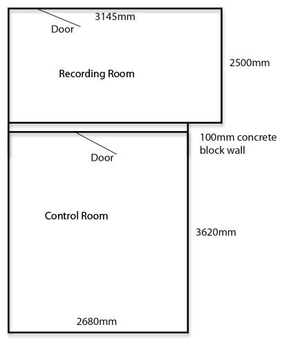
The room dimensions are 2680mm x 3620mm, I have a second room which is 3145mm x 2500mm. The studio is a garage, the construction is double wall (cavity wall).
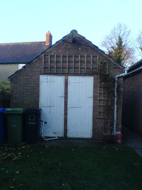
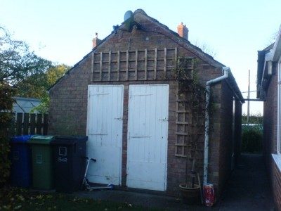
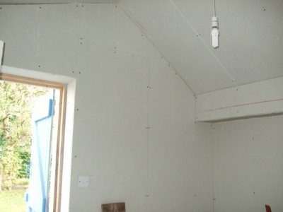
Image 1.jpgThe existing construction is a brick built garage, the outer wall being traditional brick, the inner wall concrete block. The dividing wall between the two rooms is concrete block, single block of 100mm. The roof is pitched, with concrete tiles. The floor is concrete. The ceilings are being removed; this is in anticipation of installing a vaulted ceiling. The pitch is along the full length of the garage, the height of the pitch internally is 3365mm.
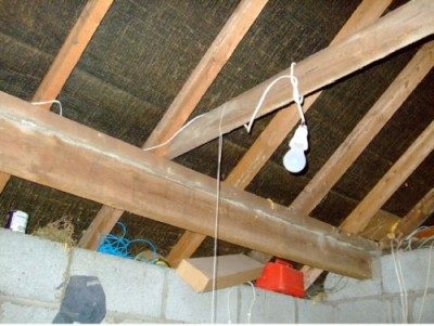
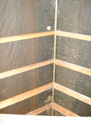
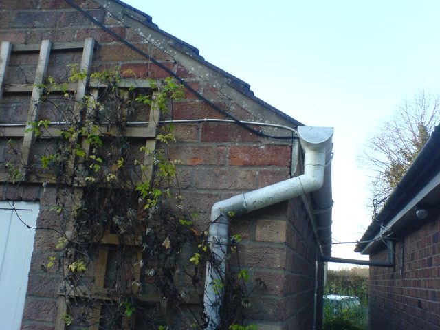
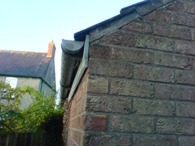
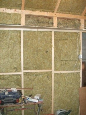
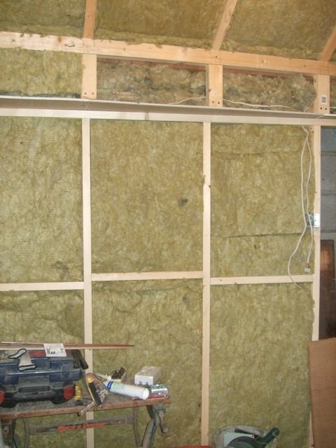
Image 2.jpgimage 3.jpg
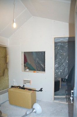
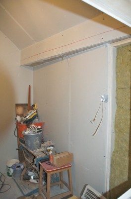
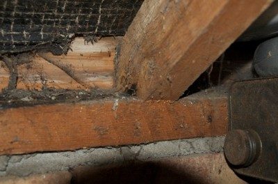
The above photos show the pitched roof and the purling that extends along the roof line, this is effectively the line of the wall if the dog leg was not there.
The height of the two sidewalls in the recording room are 1980mm (right photo) and 2200mm on the opposite wall. Again this is due to the dogleg in the wall. In the control room the wall height is 2200mm on both walls.
Budget - prefer to keep it under £600 but can go more if necessary.
My question is will the design seen below be a good starting point. I have rear ported PMC TB1 monitors which I would rather not surface mount.
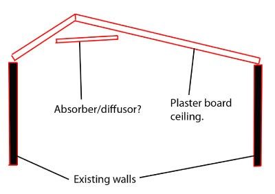
I hope I have provided as much in formation as required, the only thing I have not considered is the ceiling. I plan to vault the ceilings:
image 4.jpg
Image not preserved: image 5.jpg
Any help you can offer in making the design work will be very greatly appreciated.
Thanks
Paul Walker
Lincoln
England
Hai Paul, I'll keep it short if that's okay.
You current building sounds like a very good starting point. Double walls, concrete etc. excellent. That is, if it's really closed. And the double walls are prolly connected somehow. Well, sometimes you've gotta work with what you got.
The roof seems like your current weakspot. But, that's fixable. (if only you could add a concrete ceiling... gheh)
your (basic) design looks okay. If I had a roof like that I'd keep it open, just as your design. cool. you CR looks cool too. I can see you did your "homework". The innerwalls, however, I'm not too sure about since you already got a 2 leaf system. But if you keep them "solid" somehow... and afterall; if that's how it is, that's just how it is.
You don't "need" your monitors mounted in the wall. But use solid stands. Build an RFZ around them to have a natural and transparent mixing position.
Overall, a good plan so far!
Now, let Stu do his thing ;) (warning; lotsa text comming up)
cheers.
Just wondering if anyone could give me any advice on the above schemes.
Do you require further information maybe?
Thanks in advance.
Regards
Paul Walker
Dear All,
I have tried to 'model' the studio design I'm considering in sketchup. Please could someone review the model and comment on the position of the slot resonators (shown as grey slabs).
Are there any improvements on the shape of the rooms?
The wall construction will be standard frame and plaster board (double skin). I will put a double fire door between the two rooms.
I'm getting ready to start putting the first frames together, any help much appreciated.
Thank you.
Paul
"The roof is pitched, with concrete tiles.... The ceilings are being removed; this is in anticipation of installing a vaulted ceiling."
These modifications you are doing to the ceiling/roof, is this with the help of a professional or are you simply pulling out boards to do what you want?
A tile roof is heavy by design, the framing is more and the tiles weigh more then a standard asphalt roofing system. Buildings that are up to >code< are not necessarily overbuilt. Far from it. Meeting code is the equivalent of, if this were a school grading system, getting a "C". So anything that takes away from this effectively reduces the grade. Remove enough or add too much and you could be graded an "F". And an F is the same in all countries, failure. In this case structural failure.
The "anticipated vaulted ceiling" which will require more framing/weight on the existing walls comes to mind. Even if you do not add additional framing, and for this to be correctly built you will have to, the additional sheetrock alone, with the deleted joists that at one time tied the walls together and maintained the roof against external environmental conditions will be an issue, if you have not taken this whole structure into consideration.
Hello again, just been building the isolation room, photos to follow.
Just need a little help with the layout of the control room. I've turned things round since my last post and wondered if anyone can comment on the orientation of the room. I had the monitors firing down the length of the room before, now they are down the width. Please see the diagram attached.
Any help would be apprieciated.
Thanks
Paul
I had the monitors firing down the length of the room before, now they are down the width.
Then you had it right before! Why did you change that?
I'm also wondering why you have a bass trap sunk into the middle of one wall.
It would be much better if you were to do your plans in SketchUp, as most people do here. Hand-drawn sketches on paper scanned to PDF makes it hard to figure out. For example, it looks like your CR side walls are at different angles, the corner traps are extremely small, and the room is not symmetrical. Maybe that's just because the drawing isn't to scale?
- Stuart -
Hello Stuart,
I have attached a rough skp file, I'm not good with it, so that's why I normally do drawn sketches!
The door and window are in the right place in the control room.
I wonder if you could advise on how you would set the room out?
Thanks
Paul
Hi Paul. I'll try tto help you but I need some info. First off, I'm pretty good with Sketchup, so I downloaded your file. Unfortunately, your model is filled with inconsistancies, so I'm in the process of rebuilding it to reflect reality and make it easier to work with...ie..components and groups. I try to model with as accurate dimensions and elements as possible, so I REALLY know what I'm working with. A model is only as good as DIMENSIONAL objects. Drawing interior objects as a plane does not reflect what it may really turn out to be, which can alter interior space. Hence working with objects as they really are.
The first problem is your 100mm block size. From your pictures, it appears that they are actually 215x215x440mm blocks. The reason is, the thickness of the blocks affect the actual wall thickness. Which affects everything else. Not that it matters intirely on this scale, but to when you want something to turn out as designed...well, then it does. So I'd like to confirm the block size and the partition wall thickness. Maybe some dimensions of the door or window in that wall as well.
1. The 100mm size looks too small in relationship to the lumber.
http://www.cpi.ie/images/uploads/6448_c ... blocks.pdf
2. I assume the rafters are fastened to a wood plate on top of the concrete blocks, but assumptions can cause problems later. Are they and if so what are the nominal dimensions of the plates and rafters? Do the rafters have a birdsmouth cut? Can you show any pics.
3. In the picture of the beam, what is happening up behind it on the other side of the wall. Looks like some kind of wood element but I can't make it out. Also, is the top of the beam inline with the top of either a wood plate beyond, or the concrete block? If there are no plates(which would be ludacrous, otherwise what would the rafters be nailed to? :P ) how are the rafters fastened? Also, what are the nominal dimensions of the beam?
You might have already gone beyond the planning stage by this point. If so, no prob. But if you want me to continue, ok. The goal is to get the file to a point where you can work with it easy. I'll include some elements that will also make it easy for you.
Oh, you show a block gable end. Is it really block? At both ends? Usually, thats not the case, but there are always exceptions. How bout the rafter tails? Any exterior pics?
fitZ :)
Can I firstly say your help is really appreciated and the pictures look awesome!
I'm really busy tonight so this will be brief, but I promise to come back to you as soon as possible.
1, The block s are 450mm, 220mm, 100mm L H W.
2, Yes there is a plate line, and yes there is a birds mouth. Dimensions to follow....
3, Ok, the plate line runs through the wall, but the support lintel (wooden beam) finishes on the inside skin. So you would need to drop the wooden beam and run the plate line across the top of it.
Both ends are gabled.
As you will see I have gone a good way with the isolation room, but I have done nothing with the control room, really this is the room I'm thinking hard about.
I have had further ideas which I will try and draw up to show you.
Thanks again for all your help I really do appreciate it.
BTW the doors seen in the outside shots of the garage are not all in use. The right hand door is the one which is being used, the left hand door has been blocked up with the concrete blocks, and there is a door along the corridor between the garage and the house, this has also been blocked up. Future plans are to brick-up the outside too.
Regards
Paul
[quoteCan I firstly say your help is really appreciated and the pictures look awesome!
][/quote]
No problem. Oh, thank you. Appreciation is my pay. :mrgreen: AND, I ALWAYS learn something new from every project, whether it be a new Sketchup trick or some material or some design element. Like this...
1, The block s are 450mm, 220mm, 100mm L H W.
:shock::roll::mrgreen: I should have guessed. Its ALWAYS like that. geesh. Never ceases to amaze me. Now you know WHY I ask these questions.
With blocks I assume, as the one you show is. Man, whoever did that must have been a mason. :mrgreen: Holy mackeral, what a lot of work cutting those blocks at angles. Again, learn somthin nu evra daigh!
Ok, I'm outta time too. Talk later.
fitZ
Hello Paul. Well, you really have progressed since your first post. Ok, I guess I need some more info. From the pics, I am assuming you are furring out the block walls, inserting some type of insulation, and shiething the interior with drywall..in effect giving you a two leaf assembly.
Questions.
1. From the pictures, I can't tell if you've already furred out the CR and installed the insulation or what. Is that your intention?
2. What is the depth of the furring(which is the airgap depth).
3. What is the overall thickness of the drywall? In otherwords, if more than one layer, how thick is the combined layers.
4. From your Sketchup file, it looks like you were intending on building a splayed wall on each side of the block partition wall. In this set of pictures(because of the window) it looks like you have at least drywalled one side of the block wall. Are you drywalling BOTH sides and THEN building some kind of splayed wall also? I'm trying to determine what your intention is with all the splayed walls in the rooms. In the Sketchup file, they are shown as a simple plane, which tells me nothing other than a surface. Its difficult to tell exactly what you've built already in relationship to your plan.
For instance, in the last few pictures, I see what appears to be a closet door, with some depth between your new wall and the existing block wall. Did you splay that wall? What other walls are already splayed?
5. What are the wood members hanging from the cieling for?
6. Can you lable North/South, and take a picture of each wall of the Control Room as it is today? Or at least describe EXACTLY what you've done and your intentions. The reason is..I don't want to waste yours or my time modeling something that does not reflect the current status of the rooms. Thanks
fitZ
Hi fitZ,
I have made some progress, not enough for me!
Just so we are clear the room in the photos is actually the recording room (iso booth) for vocals and drums etc. as seen in the image below.
Image not preserved: Image 1.jpg
Yes I have splayed the walls as per the following image:
Image not preserved: image 5.jpg
As you will see I have annotated the image with the compass points as requested, the following images are of each of the walls:
EAST WALL
Image not preserved: DSC_4519.jpg
WEST WALL
DSC_4518.jpgNORTH WALL
Image not preserved: DSC_4522.jpg
SOUTH WALL
DSC_4521.jpg
Not preserved: DSC_4521.jpg
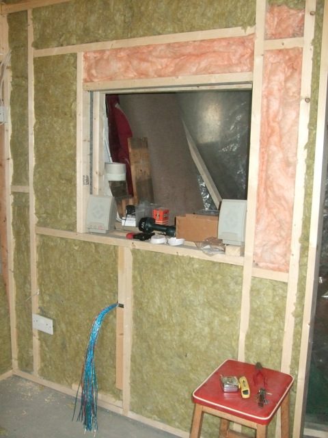
The recording room is the only room I have worked on so far. The timber used to stud out was 2.5" by 1.5" the insulation used to 'Fur' was 70mm thick (1200 x 600mm) 45Kg/m3. The thickness of the dry wall is 1" (25mm) this was carried out by applying the first layer and caulking the edges, then apply the second layer, off set so the edges were not in the same place.
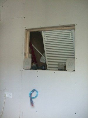
The west wall is splayed, a frame was built using the same size timber, furred and dry walled, I did not dry wall the concrete block first, this due to the fact that I need to remove some of it to installed the window and door. The areas between the doors and window are have been framed and will have insulation and drywall on both sides.
The 'closet' you speak about has been drywall (1" thick) on all three sides and filled with insulation ready for a slotted front resonator bass trap.
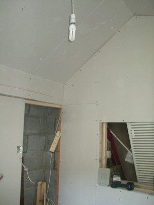
The wooden members are just holding the insulation in place prior to the dry wall by placed on the ceiling. They have since been removed and dry wall keeps the insulation in it's slots!
In all cases the walls and ceiling will be skimmed with plaster forming a good seal and a good decorating surface, I thick you guys in north America usually caulk and sand, we go one step further and I will employ a plaster to get this portion of the work completed.
I will need add further photos on another post.
Paul
I needed to check the internal structure of the roof plate joint.
The following photos shows the roof timbers (1.5" x 4") and the plate (1.5" x 4") you can see the inside of the barge board. Not birds mouthed as I previously thought. :roll:DSC_4510.jpgI think I have answered all your questions so far! :P
I will be travelling next week (Canton Ohio). I will be able to get online, so I hope to be able to anwer any further questions.
Thank you very much for all your help.
:D
The following photos shows the roof timbers (1.5" x 4") and the plate (1.5" x 4") you can see the inside of the barge board. Not birds mouthed as I previously thought. :roll:
This is a modified birds mouth, for whatever reason it would have mattered. It's a typical seat/plumb cut with the rafter tail bobbed.
I have just realised I have marked the South and North Walls the wrong way round on the photos shown.
The drawing is correct, the photos are wrong way round!
Sorry for any confusion.
Paul
Hello again. Well, I bet you wondered what happened to me. I haven't forgotten about you Paul. I've just got lots of irons in the fire, but I've managed to get this far. Its late, and I'm tired. Been framing this thing all day. :mrgreen: I'll be back with some finished stuff for you soon.
fitZ :D
Oh my word! That looks amazing! :D
What would you think about rotating the seat position through 90 deg to the right for mixing, but have a wrap around desk so you can track in the position you have chair now?
I wondered if that would actually give the best of both worlds, i.e. monitors shooting down the length of the room, but still being able to have eye contact with the 'performance'.
Would be interested in your opinion on that one.
Your sketch-up skills are truly impressive.....
I really appreciate your time and effort....thank you very much.
I have suppliers (investment casting) in Portland Oregon, are you anywhere close to Portland?
I was in Ohio last week, so I'm glad in a way that you had other 'irons'...
Thanks again and speak soon.
Paul
What would you think about rotating the seat position through 90 deg to the right for mixing, but have a wrap around desk so you can track in the position you have chair now?
Well, for what its worth now. Your probably finished building it already :mrgreen:
There is no reason for it to matter to anyone, especially someone seated in the construction trades that is far aware that you cannot have a rafter without having a birds mouth or some portion there of.
Thanks for your participation,
Brien
There is no reason for it to matter to anyone, especially someone seated in the construction trades that is far aware that you cannot have a rafter without having a birds mouth or some portion there of.
Hmm, thats odd. I searched all my replys to find where I said it did. Of course it wouldn't matter to you However, YOU ain't modeling it. Just the same, I'll file your observation under blindingly obvious.
In the meantime, perhaps you could post your own succinct 3d delineation. I'd be delighted to learn from it since you are awarely seated in the construction trades.Then I can thank you for your participation.
btw, heres a tip why it mattered to me. I've seen ALL these conditions. Small buildings get built by novice DIY'ers all the time with no permits etc, regardless what matters to a carpenter.
Paul, my hosting site is experiencing "technical issues" on their servers. I'm sure it will be up and running soon. The reason I use a hosting site instead of uploading them here is the SIZE of hosted pics. For some reason, the pixel thing is different when I link to a hosted picture. See the difference between the last jpg, and the ones of the conrol room. They're BOTH 700 pixels wide. Go figure. :?
Compare this to the previous one . Both are 700.