Well, things are moving along. I framed up the rear wall of the Control room Saturday. The structural part of it, that is. And I laid-out the framing for the slot resonators, and the up-lighting "bench".
The area for the slot resonators are a maximum 24" deep, and a minimum 14" deep and about 48" across. Seems kinda big to me. Attached is a picture of the base plates laid out on the floor. I'll end up with a rear wall height of about 11 feet. The functionality of the slot resonators will sort of "end" at about 9' high. It'll still appear to go from floot to ceiling, but that additional 2 feet will actually allow me to install the return air vents for the CR in that void.
The bottom of the slot resonators are of course sealed by the floor, and a piece of 5/8" plywood will seal the top at 9'. Again, above that is the void for the return air vents.
Sound like a plan?
Any thoughts on the dimensions of the Slot Resonators?
CR Rear Wall Question
-
Michael Jones
- Posts: 138
- Joined: Tue Mar 11, 2003 4:03 pm
- Location: Austin
- Contact:
-
Michael Jones
- Posts: 138
- Joined: Tue Mar 11, 2003 4:03 pm
- Location: Austin
- Contact:
-
Michael Jones
- Posts: 138
- Joined: Tue Mar 11, 2003 4:03 pm
- Location: Austin
- Contact:
...Feel like I'm talking to myself here....
So, I ran the helmholtz resonator spread-sheet, and with that size, and those dimensions, I should be able to attenuate frequencies down to about 200 Hz.
Not bad, I guess.... I was hoping the increased distance from the wall would allow for a little lower frequency attenuation... but apparently not.
-
giles117
- Senior Member
- Posts: 1476
- Joined: Sat Jun 21, 2003 2:42 am
- Location: Henderson County
- Contact:
-
Michael Jones
- Posts: 138
- Joined: Tue Mar 11, 2003 4:03 pm
- Location: Austin
- Contact:
-
knightfly
- Senior Member
- Posts: 6976
- Joined: Sun Mar 16, 2003 11:11 am
- Location: West Coast, USA
Michael, sorry it took so long to answer - I've been waiting for a reply from John, because I'm a little confused as to your use of slots in that location. From what I've seen of your plan, it looks to me like you're kind of close to the mix position to use reflective or diffusive treatments there, yet you're showing both in your plan.
As to variable depth/slat/slot widths giving a wider frequency range - Barefoot disagrees with that concept; the wavelength at 200 hZ is 5.65 feet and low frequencies are basically non-directional, so a resonator that's less than probably 2 wavelengths or more in dimension would tend to just average out over the surface of the resonator. Not that the resonator wouldn't work, just not as assumed. You could, if you add "separators" between sections inside the trap, create separate resonators with different average depth of cavity if there's a need - one tricky part is deciding ahead of time just which frequencies are going to be a problem. With splayed walls, modes are still there but not as easy to predict pressure zones, etc - the only way I know to get close to what frequencies may be problems is to take the AVERAGE dimensions in all three axes and calculate modes from that. Any modes that are supported in more than one axis would be my first choice for trap tuning.
If your head will be less than 10-12 feet from the rear wall, I would either use straight broadband absorption (703 across the front of the cavity) or keep the slats but put 1" 703 panels in FRONT of them (spaced by at least an inch) to avoid early reflections back to the mix position.
Hope that helped, maybe you could clarify your intentions??!? Thanks... Steve
Soooo, when a Musician dies, do they hear the white noise at the end of the tunnel??!? Hmmmm...
-
John Sayers
- Site Admin
- Posts: 5462
- Joined: Mon Jan 27, 2003 12:46 pm
- Location: Australia
- Contact:
-
Michael Jones
- Posts: 138
- Joined: Tue Mar 11, 2003 4:03 pm
- Location: Austin
- Contact:
OK. You guys are freaking me out here, so before I have a panic attack  let me clairify a few things to make sure we're on the same page, and that I'm not butchering the terminology.
Let's start with the control room size:
Front Wall
13'-7"
Side Walls
11'-10" Splayed 12 degrees
at that point the 12 degree angle reverses and continues for 6'-6" to the rear wall.
Length
From front wall to rear wall 18'-0"
Mix position
6'-6" from the FRONT wall. (Leaving 11'-6" from my head, to the rear wall)
These are actual "As-Built" dimensions.
Now, some terminology:
When I say "slot resonators" I mean these:

Now these appear to be set, in rear corners, at 45 degrees. The ones I have in mind would be at 22 1/2 degrees.
My original plan, the one on the Johns Studio's Under Construction Site, shows an RPG type diffuser on the rear wall. I'll concede that that probably won't work, and in its place will be an angled absorber - Cloth covered 703.
I see control rooms designed with dimensions similar to mine in length that DO use slat resonators on the rear wall. So, why not here?
Maybe my "Studio Vocabulary" isn't where it should be?
Let's start with the control room size:
Front Wall
13'-7"
Side Walls
11'-10" Splayed 12 degrees
at that point the 12 degree angle reverses and continues for 6'-6" to the rear wall.
Length
From front wall to rear wall 18'-0"
Mix position
6'-6" from the FRONT wall. (Leaving 11'-6" from my head, to the rear wall)
These are actual "As-Built" dimensions.
Now, some terminology:
When I say "slot resonators" I mean these:
Now these appear to be set, in rear corners, at 45 degrees. The ones I have in mind would be at 22 1/2 degrees.
My original plan, the one on the Johns Studio's Under Construction Site, shows an RPG type diffuser on the rear wall. I'll concede that that probably won't work, and in its place will be an angled absorber - Cloth covered 703.
I see control rooms designed with dimensions similar to mine in length that DO use slat resonators on the rear wall. So, why not here?
Maybe my "Studio Vocabulary" isn't where it should be?
-
knightfly
- Senior Member
- Posts: 6976
- Joined: Sun Mar 16, 2003 11:11 am
- Location: West Coast, USA
Michael, panic attacks are for AFTER you've built too much and it's wrong - I've gotta play "honey-do" for about an hour, but I'll get back to you early this evening at latest - first, your CR is right at 20 milliseconds delay from your head back to your head off the rear wall. Second, your surrounds will cause early reflection problems with slats there. Third, what John drew will fix it all. More in a bit... Steve
Soooo, when a Musician dies, do they hear the white noise at the end of the tunnel??!? Hmmmm...
-
knightfly
- Senior Member
- Posts: 6976
- Joined: Sun Mar 16, 2003 11:11 am
- Location: West Coast, USA
OK, honeydew done 4 now - Here's a quick markup of your CR, with the two reflection paths I was concerned with added in.
I converted your CR drawing to vector, but only cleaned up the angles that matter when doing a crude ray-trace, so most of it might look kinda wierd - the reflection angles, however, are exact. I only drew one side, but the other would be identical.
Note that the path length we're concerned with is from your head to the back wall and return, which as I said earlier would give about 20 ms delay. This is right at the go/no-go area as far as smearing is concerned, and I personally wouldn't take the chance.
In the case of the surrounds, the path we're concerned with is the difference in length between the direct path and the reflection path, which are only about 4.6 feet, or 4 ms, different. This is definitely too soon for reflections to be happening.
So far, all the 5.1 mixers I've known of are tending to absorb any wall that has a speaker aimed at it, then putting the ambience back with DSP. This is why I'm looking at reversible inserts for the front half of my CR, absorbent side for 5.1 and reflective panel trap side for stereo, for RFZ.
That's about all I can think of at the moment, I hope I clarified my concerns. Had I noticed any of this earlier, I would have brought it up sooner. Hopefully it's not too late to still consider it a relatively minor "whoops"... Steve
Soooo, when a Musician dies, do they hear the white noise at the end of the tunnel??!? Hmmmm...
-
Michael Jones
- Posts: 138
- Joined: Tue Mar 11, 2003 4:03 pm
- Location: Austin
- Contact:
Wow, Steve, thanks a lot.
I'm glad I asked. Saved me a ton of headache and heart break.
So... no slot resonators in my CR. I guess....
I thought I really had this all figured out, then along come you guys. Now I feel really stupid!
Now, John's pic shows bass hangers... behind what? Cloth? And no 703 in the bass hanger cavity?
I'm doing a quick re-charge on the camera. Maybe I can get you to look at something else? In the live room. I'm probably beating another dead dog in there!
I'll post a pic......
-
giles117
- Senior Member
- Posts: 1476
- Joined: Sat Jun 21, 2003 2:42 am
- Location: Henderson County
- Contact:
I have to add this, no Slot resonators on the REAR wall of your control room. On the side walls at mix position is fine. Justr not on that rear wall.
That framing you laid out for your resonators.... I'd do what I did in the rear of my control room. That would be all absorptive with4' Mineral wool covered with fabric.
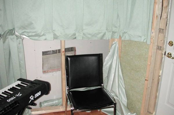
This is what I did. I left a piece of fabric off in the pic for demonstration purposes. It's basically the saem thing John and Steve are sying just my interpretation.
http://www.johnlsayers.com/Studio/Image ... _wall1.JPG
That is a portion of my rear wall and you will notice the frame and the mineral wool in the frame with the cloth stapled to the front of the frame.
Bryan Giles
Sorry should've moved the chair.
That framing you laid out for your resonators.... I'd do what I did in the rear of my control room. That would be all absorptive with4' Mineral wool covered with fabric.
This is what I did. I left a piece of fabric off in the pic for demonstration purposes. It's basically the saem thing John and Steve are sying just my interpretation.
http://www.johnlsayers.com/Studio/Image ... _wall1.JPG
That is a portion of my rear wall and you will notice the frame and the mineral wool in the frame with the cloth stapled to the front of the frame.
Bryan Giles
Sorry should've moved the chair.
-
Michael Jones
- Posts: 138
- Joined: Tue Mar 11, 2003 4:03 pm
- Location: Austin
- Contact:
Yeah, I've been checking out your progress too giles, thanks for the input.
Steve, In the live room I have these colums built. They're there for elec. conduit, lighting, and outlets. Having these colums eliminates any penetrations in the exterior wall. That's the basic functionality. On the face of these colums I was going to add RPG style diffusors, and between them (Against the wall) I'm going to build some of John's Varible bass absorbers/diffusers.
This first photo shows the wall with colums that would basically be the .... how should I say this... non-attack side for the 7'-2" grand I have... so the lid would open AWAY from that wall... basically into the live room.
The second pic is the OPPOSING wall - located some 30' away. You can see that it has only ONE column which is centered between the other two on the opposite wall. Same treatment here.
If you notice, in the first pic, theres a small "problem area" between the column and the wall separating the live room from the drum room. It's just kind of a small niche or corner created by the column and the wall.
Any thoughts on that, and with the general scheme of treatment for this portion of the live room. Remember, there's a large grand going in here.
OK. Pic #1
-
Michael Jones
- Posts: 138
- Joined: Tue Mar 11, 2003 4:03 pm
- Location: Austin
- Contact:
-
Michael Jones
- Posts: 138
- Joined: Tue Mar 11, 2003 4:03 pm
- Location: Austin
- Contact: