Well, here we are. Design turns into reality Monday morning (this should have been posted Sunday). I’m intending to take pics along the way to document the fun, but don’t get too disappointed if the lazy creeps out.
Here is an overhead of the concept. Single room studio (top left) with a machine room (top left) to house the hot and noise prone. The studio space is a room within a room design, isolated save a shared concrete floor. Access to the breaker box will be via an opening face in the side wall Helmholtzer (thanks Bruce).
On with the fun!
BF’s Basement Studio Build Journal
Originally posted at johnlsayers.com, topic 9255.
Day 0, Sunday: A bit of prep before the fun ensues
Sunday night. The evening before D day. Spent a few hours tidying up and stuffing pink stuff overhead.
External image, not preserved — original: http://i188.photobucket.com/albums/z78/BF_Studio/00-Day0stuffingthepinkup.jpg
Day 1, Monday: Bring the funk, bring the noise… or, where we going to put all this stuff?
Monday begins with a 3 egg omelet in trimester 3 with salsa, cheese and sausage. Powered up and ready to go. 7:00 sees the first bits of actual progress, as deliveries and HVAC appointments are confirmed. One delivery confirmed as ‘We told you Monday morning!’.. c’mon, I’m ready to bounce off the walls and they have yet to be built. No need for attitude this early in the project.
Lumber, drywall, MDF and hardware arrive shortly after,
External image, not preserved — original: http://i188.photobucket.com/albums/z78/BF_Studio/1.01Budworkshistriwheelforktruck.jpg
And Bud does a bang up job of working materials into the garage as well as the lift will allow. External image, not preserved — original: http://i188.photobucket.com/albums/z78/BF_Studio/1.02Delivery1.jpg
Rory arrives prepared to put the hurt on some timber.
External image, not preserved — original: http://i188.photobucket.com/albums/z78/BF_Studio/1.03Roryprepstoputthehurtonthetimbers.jpg
A few moments of brain storming and we select our creative entry point for the 16ft lumber. It turns out so efficient we stuff everything that will fit through the hole.
External image, not preserved — original: http://i188.photobucket.com/albums/z78/BF_Studio/1.04Creativeentrypointsfor16ftlumber.jpg
Lumber down,
External image, not preserved — original: http://i188.photobucket.com/albums/z78/BF_Studio/1.05Lumbermakesitdownstairs.jpg
drywall and MDF down,External image, not preserved — original: http://i188.photobucket.com/albums/z78/BF_Studio/1.06DrywallandMDFmakesitdownstairs.jpg
and down wanders the nice gent from General Insulation. I understood the concept that 2'x4'x2" stacked up quick, but I seem to have failed to grasp the number of cartons vs the size of the garage. External image, not preserved — original: http://i188.photobucket.com/albums/z78/BF_Studio/1.07OC703delivery.jpg
and more…
External image, not preserved — original: http://i188.photobucket.com/albums/z78/BF_Studio/1.08OC703wherearewegoingtoputallofthis.jpg
creeping into the living room..
External image, not preserved — original: http://i188.photobucket.com/albums/z78/BF_Studio/1.09moreOC703.jpg
And into the workspace in the basement.
External image, not preserved — original: http://i188.photobucket.com/albums/z78/BF_Studio/1.11moreOC703II.jpg
A series of HVAC guys came and we discussed the needs and our desires for the project. They drafted their plans while eyeing the competition, and we went over the fine points of each. We then left them in the basement to battle to the death, each armed with a carpenter pencil and a sheet of 703 strapped to an arm as a shield, while we stepped upstairs to grab a bite for lunch.Day 1, Monday, continued: HVAC
Armed with marzetti and cornbread cobbler we wander back down to find the victor. The sketch is a guesstimate on location / dimensions. The black is existing lines supplying the living and family rooms above. Red is 7in flex duct supplying fresh air, one run to the rear of the studio space to minimize sound transference through the system, the other to the rear of the machine room. Blue is 7in flex duct return lines located where most of the heat produced by gear is likely to occur. This sounds like it all makes sense to me but the air side is not my cup of tea, i.e. comments encouraged. Detailed pricing should come Tuesday and they can run everything Thursday morning, so if anyone has input here I can pass it along before then.
Day 1, Monday, continued: The build begins
After clearing the carnage of the HVAC Highlander episode, we begin applying the FRK 703 to the portion of the block that will become the inside of the outer wall. Framing on the rear inner wall begins as well.
External image, not preserved — original: http://i188.photobucket.com/albums/z78/BF_Studio/1.12Constructionbegins.jpg
External image, not preserved — original: http://i188.photobucket.com/albums/z78/BF_Studio/1.13OC703sidewall.jpg
Ya, I need to take care of that coax and CAT5 rat's nest before people arrive tomorrow.
Framing for the inner rear wall is done and work begins on the inner front wall. Block wall continues to be treated. External image, not preserved — original: http://i188.photobucket.com/albums/z78/BF_Studio/1.14Backwallupmore703.jpg
A bat of 703 FRK is cut to fit the water line,
External image, not preserved — original: http://i188.photobucket.com/albums/z78/BF_Studio/1.15Watermainfitting703.jpg
And the removed slots trimmed and replaced. External image, not preserved — original: http://i188.photobucket.com/albums/z78/BF_Studio/1.16WaterMainfitting703II.jpg
At some point while framing, Rory standing next to the treated block wall comments ‘this insulation really kills the sound’. Thinking this is a joke on the growing wall of rigid insulation I laugh it off, but he convinces me to hold my head a few inches off the wall.
External image, not preserved — original: http://i188.photobucket.com/albums/z78/BF_Studio/1.17Whattheheck.jpg
From less than a foot away the sensation is bizarre! Almost as if it is throwing off your equilibrium, or the air pressure is notably different on that side of the head. I don’t know why I got such a kick out of this.
Day 1 ends with the block pretty much treated, the front and rear inner walls framed, and the left inner side wall cut and marked. This side wall is going to be the most interesting of the lot I think. The wall will have to be built out to create the cavity for the breaker, network switch and PIX firewall. The plan is to build out from the frame to within a half inch of the block, and bridge the gap with backer rod and OSI SC-175 to create the seal for the resonator while maintaining isolation.
External image, not preserved — original: http://i188.photobucket.com/albums/z78/BF_Studio/1.18Day1isover.jpg
With the smell of studio in the air, the gear that has been living in the loft since June begins to stir in antici…
External image, not preserved — original: http://i188.photobucket.com/albums/z78/BF_Studio/1.19Withthesmellofstudiointheairthegearbeginstostirrintheloft.jpg
Pation!all that in one day? DANG!
"Dang" is right! Wow! Some of you guys are serious about this stuff!!! It takes me forever to make the kind of progress that you and Lou make in one day! Great job!all that in one day? DANG!
Day 2, Tuesday: I love it when a plan comes together
An early start again today, and another big omelet to kick it off. I re-route some wires and clear up the cable rat’s nest above the breaker. Rory arrives with more tools
External image, not preserved — original: http://i188.photobucket.com/albums/z78/BF_Studio/2.01Partnerincrimearriveswithmoretools.jpg
and we get to work.
One of the few walls that didn't get torn out needs cut down so that the outer wall can make a seal on the block wall.
External image, not preserved — original: http://i188.photobucket.com/albums/z78/BF_Studio/2.02Cuttingoldwall.jpg
We begin to frame the left inner wall (the one I mentioned would be fun).
External image, not preserved — original: http://i188.photobucket.com/albums/z78/BF_Studio/2.04Leftinnerwall.jpg
The first layer of the inside-out portion of the wall starts to take shape,
External image, not preserved — original: http://i188.photobucket.com/albums/z78/BF_Studio/2.05Insideoutportionofleftwall.jpg
and we begin to work on the resonator enclosure that will house the breaker.
External image, not preserved — original: http://i188.photobucket.com/albums/z78/BF_Studio/2.06breakeralcoveframe.jpg
We are still waiting for the Green Glue to arrive, so we move on to build the plug for the basement window,
External image, not preserved — original: http://i188.photobucket.com/albums/z78/BF_Studio/2.07Windowplug1.jpg
fill it with a few trimmed chunks of the FRK, External image, not preserved — original: http://i188.photobucket.com/albums/z78/BF_Studio/2.08Windowplug2.jpg
and ease it into place and seal one of the major isolation concerns.
External image, not preserved — original: http://i188.photobucket.com/albums/z78/BF_Studio/2.09Windowplug3.jpg
The Green Glue arrives right on cue. External image, not preserved — original: http://i188.photobucket.com/albums/z78/BF_Studio/2.10Greengluearrivesjustontime.jpg
External image, not preserved — original: http://i188.photobucket.com/albums/z78/BF_Studio/2.11Greenglue1.jpg
External image, not preserved — original: http://i188.photobucket.com/albums/z78/BF_Studio/2.13Greenglue6.jpg
Layer two goes on the inside-out wall, External image, not preserved — original: http://i188.photobucket.com/albums/z78/BF_Studio/2.14Leftinnerwalllayertwo.jpg
and it is glues, screwed, and mudded.
External image, not preserved — original: http://i188.photobucket.com/albums/z78/BF_Studio/2.16Leftinnerwallbreakerframeandtwolayerinsideout.jpg
The left inner wall goes up. External image, not preserved — original: http://i188.photobucket.com/albums/z78/BF_Studio/2.17Leftinnerwallup.jpg
A few shots of the breaker.
External image, not preserved — original: http://i188.photobucket.com/albums/z78/BF_Studio/2.18Breaker.jpg
External image, not preserved — original: http://i188.photobucket.com/albums/z78/BF_Studio/2.19Breakerframed.jpg
This leaves about a half inch to the block wall. The gap will be filled with backer rod and sealed with OSI SC-175. External image, not preserved — original: http://i188.photobucket.com/albums/z78/BF_Studio/2.20Breakergap.jpg
Not build related, but the final delivery of the day was a nice break.
External image, not preserved — original: http://i188.photobucket.com/albums/z78/BF_Studio/2.21toft.jpg
But no time to play, we must push on. The front and rear walls come down and Rory leaves for his Graduate class. I continue on getting both layers on the rear wall and a single on the front...
External image, not preserved — original: http://i188.photobucket.com/albums/z78/BF_Studio/2.22Frontandrearwallsdown.jpg
That is until a clumsy step puts me through the center drywall portion. Well, the rear wall is ready for the door External image, not preserved — original: http://i188.photobucket.com/albums/z78/BF_Studio/2.23Rearwallreadyfordoor.jpg
and I clean up and call it a night.
Items of note, Rory told me to wear some real shoes tomorrow. I'll see how I feel about that in the morning.Day 3, Wednesday: Four walls makes a room
Hit the snooze a few times, but managed to be up and mostly awake when Rory arrived. Threw us some eats on the stove and headed down to the basement. We made quick work of the rear inner wall, putt the door into place, raised and positioned the wall. Man, these things start to get heavy with a few layers and a door on them.
External image, not preserved — original: http://i188.photobucket.com/albums/z78/BF_Studio/3.01Innerrearwallwithdoor.jpg
The front inner wall gets some love next. External image, not preserved — original: http://i188.photobucket.com/albums/z78/BF_Studio/3.02Innerfrontwall1Greenglue.jpg
External image, not preserved — original: http://i188.photobucket.com/albums/z78/BF_Studio/3.09Innerfrontwall8.jpg
Ya, I opted for the shoes today.
And we have wall number three.
External image, not preserved — original: http://i188.photobucket.com/albums/z78/BF_Studio/3.10Innerfrontwallup.jpg
We have taken to calling the area behind the rear wall ‘the corner of confusion’ due to the two foot wide space enclosed in 703.
External image, not preserved — original: http://i188.photobucket.com/albums/z78/BF_Studio/3.113wallsofcontrolroom.jpg
Rory exits the corner of confusion, but the shot show three walls of a room.
The fourth wall gets framed and the door added. From here on out the ply and drywall will have to be hung vertical.
External image, not preserved — original: http://i188.photobucket.com/albums/z78/BF_Studio/3.134wallsofcontrolroom2.jpg
The rafters get cut and notched to allow them to hang below a stabelizing beam running perpendicular to the floor joists.
External image, not preserved — original: http://i188.photobucket.com/albums/z78/BF_Studio/3.17Puttingraftersinplace.jpg
You can see the clearance here, External image, not preserved — original: http://i188.photobucket.com/albums/z78/BF_Studio/3.18raftersclearstructure.jpg
and how they straddle the joists,
External image, not preserved — original: http://i188.photobucket.com/albums/z78/BF_Studio/3.19raftersstraddlefloorjoists.jpg
and a shot of the brackets. External image, not preserved — original: http://i188.photobucket.com/albums/z78/BF_Studio/3.23rafterbrackets2.jpg
Tomorrow will be a lazy day (needed), just watching the HVAC guys do what they do, and maybe a bit of calking.
Well, four walls, floor and a ceiling make a room, right?Day 4, Thursday: HVAC
Tom and Bob got here around 8 this morning. These guys were fun. Got to love a couple of guys a bit rough around the edges that make the day go by having fun while actually working.
External image, not preserved — original: http://i188.photobucket.com/albums/z78/BF_Studio/4.01.jpg
The gear arrives.
The guys prep the first fresh air run, tapping into the existing systemExternal image, not preserved — original: http://i188.photobucket.com/albums/z78/BF_Studio/4.02.jpg
and notching a stabilizer for the floor joists to allow the flex duct to run above. External image, not preserved — original: http://i188.photobucket.com/albums/z78/BF_Studio/4.03.jpg
The flex comes out External image, not preserved — original: http://i188.photobucket.com/albums/z78/BF_Studio/4.04.jpg
External image, not preserved — original: http://i188.photobucket.com/albums/z78/BF_Studio/4.05.jpg
and mounted to the supply.
Run from the machine room over the control room. External image, not preserved — original: http://i188.photobucket.com/albums/z78/BF_Studio/4.06.jpg
To the back of the control room External image, not preserved — original: http://i188.photobucket.com/albums/z78/BF_Studio/4.07.jpg
and the boot mounted waiting to drop into the drywall when we hang the ceiling. External image, not preserved — original: http://i188.photobucket.com/albums/z78/BF_Studio/4.08.jpg
The the control room return. External image, not preserved — original: http://i188.photobucket.com/albums/z78/BF_Studio/4.09.jpg
External image, not preserved — original: http://i188.photobucket.com/albums/z78/BF_Studio/4.10.jpg
Fresh air to the machine room External image, not preserved — original: http://i188.photobucket.com/albums/z78/BF_Studio/4.11.jpg
and the return was constructed so it can be built into the machine room wall when constructed.External image, not preserved — original: http://i188.photobucket.com/albums/z78/BF_Studio/4.12.jpg
External image, not preserved — original: http://i188.photobucket.com/albums/z78/BF_Studio/4.13.jpg
You can see the pencil line on the floor behind, where the outer wall will sit.
Went to pick up a few more 16 ft 2x4s to beef up the rafters and now I'm off to grab a bite.
Four days down (and one mostly spent standing around) and I'm pretty happy with the progress so far.
The Mason Industries Rep has been a chore to keep on track. I need to get that taken care of before we cast the floating monitor stands.We then left them in the basement to battle to the death, each armed with a carpenter pencil and a sheet of 703 strapped to an arm as a shield . . .
:lol: :lol: :lol: :lol: :lol: :lol: That's classic!!! :lol: :lol: :lol: :lol: :lol: :lol: I love your writing style, BF! 8) And I love seeing all the pictures. Now, I did notice a few items that leave me concerned for you... Those notched joists are not going to fly... Code (I think) calls for notching no more than one third of its total height. It looks like you cut close to half. Their load bearing capacity is ]b]substantially[/b] compromised. Plus, are the 2x4s? I would think 2x6 would be the absolute minimum you'd need. Have you consulted the span calculator? :roll: Also, the framing around the door -- you definitely need king and trimmer studs. See the "Installing a door - anything I should keep in mind?" thread, which is linked from the almighty "REFERENCE AREA" announcement thread. See also Appendix B12 of Habitat for Humanity's Framing -- Wall Layout guide for illustrations of a conventional doorway. (Obviously, techniques for studio doors differ, but they usually go above and beyond conventional framing methods.) There's also the issue of the electrical service panel being concealed behind a resonator. I don't know that will meet code. :roll: I seem to recall reading somewhere once that electrical service panels can't be hidden away like that, that they have to be readily accessible in an emergency -- and recognize the fact that in an emergency, "the ones who know where it is" aren't necessarily around to advise. Come to think of it, I haven't seen a word yet about permits or inspections, so.......... :roll: Well, I don't want to "get on my high horse," but I do urge you to study the "Permits, Codes, Licenses -- and WHY YOU SHOULD CARE!" sticky thread. You are moving really fast -- which can make some of us jealous -- but I really think you need to slow down a bit, catch your breath, and make sure you're doing things safely and in a way that won't cause you later regrets. :) --Keith :mrgreen:After clearing the carnage of the HVAC Highlander episode. . .
Yes, I too have some concerns.......
As Keith noted - although he wasn't quite this positive -
Your ceiling joist are now 2x2's..........
There is no way that what you have done will support your ceiling long term............
By the way - we need a clean pic - what do you mean by "notching a stabilizer for the floor joists" ?????????
I really want to see what you did......... I say this because you don't have floor joist - you have trusses - and notching truss members is sort of a no-no -
I just want to make sure you aren't going to need a repair.........
Rod
Thanks Keith, I'm trying to keep it interesting, thus get people to continue reading and give feedback exactly like this.I love your writing style, BF! 8) And I love seeing all the pictures.
Should be cut down an inch and a half, which does put me over a third. Notching them was not the initial plan, but I forgot to account for this perpendicular member :oops: (going from left to right in the pic below) and it was a quick notion to gain the needed clearance.Now, I did notice a few items that leave me concerned for you... Those notched joists are not going to fly... Code (I think) calls for notching no more than one third of its total height. It looks like you cut close to half.
External image, not preserved — original: http://i188.photobucket.com/albums/z78/BF_Studio/3.19raftersstraddlefloorjoists.jpg
This looks like it was used to keep the joists in place during construction and doesn't seem to serve any structural need at this point. Could it be notched to allow uncut ceiling joists the clearance they need?
The ceiling joists are to have another 2x4 attached to make an L shaped beam, the calculator only seems to handle individual timbers. Any advice on this? If that cross beam could be notched to provide clearance there should be room to handle 2x6 joists. A little guidance here would be greatly appreciated. My construction experience is pretty mild (roofing, drywall and building a barn on a farm back home). While I don't mind hard work, my knowledge on on the technical side is admittedly lacking. I'm relying heavily on the guidance of a friend who has done a handful of rehabs and flips.Have you consulted the span calculator?
Man, somehow I missed this in Rod's book (even though I read it cover to cover 4 times and have gone back over various sections many times). Can I add king studs to the sides and be safe or do these walls have to be torn down? If this can be rectified without starting from scratch this would be good to know.Also, the framing around the door -- you definitely need king and trimmer studs.
Hmm, this was recommended in my design thread :?: with reference to another build that included an opening panel like this to allow access. Can a breaker not be contained in a utility closet, and could the resonator not be considered an oddly designed closet? The portion over the breaker could be left open to allow access. The loss of the resonator would be missed, but one must do what must be done.There's also the issue of the electrical service panel being concealed behind a resonator. I don't know that will meet code. :roll: I seem to recall reading somewhere once that electrical service panels can't be hidden away like that.
To my understanding as the basement was finished before we began construction the only permits required are in regards to new electrical runs. I skimmed through this thread and didn't notice it so it must only be in the design thread, but my little cousin is an electrician and everything is supposed to be kosher on his end. We are a good bit out from running electric yet an any regards. I know it probably seems like we are tearing through the project, but this is but one of a few planned 'sprints' while I have time scheduled off. I appreciate the feedback and any help you can offer on correcting the issues observed. Thanks BFCome to think of it, I haven't seen a word yet about permits or inspections
Sorry Rod, seems I'm green and using the wrong terms. The trusses have been in no way tampered with, it was this cross member shown in the pic below. This ceiling has me pretty bugged out right now. Is there any way I can get this working short of tearing the walls down and rebuilding shorter?By the way - we need a clean pic - what do you mean by "notching a stabilizer for the floor joists" ????????? I really want to see what you did......... I say this because you don't have floor joist - you have trusses
I'm so glad we have Rod's attention here. 8) I'm going to defer to his expertise on the code and structural issues.
As far as the ideas clearing the design area but not necessarily being up to code (I'm not 100% sure, as codes vary from place to place, but let's assume for the sake of argument that it's not to code), bear in mind that designs are one thing, approved and permitted designs are another. ;-)
I also caution you against assuming that just because your basement was finished before you began construction that you do not require a permit. I'm willing to bet that's not correct. My house is finished inside, yet if I wanted to remodel a kitchen or a bathroom, it would indeed require a permit in my town.
Make no assumptions on this -- always get the facts from your local municipal building department to be sure. Worst case, you tell them exactly what you plan to do and you find out you really don't need a permit, in which case you can tell me that my assumption was wrong, and that's worth something. ;-) ;-)
Hey, I just noticed this... Those doors are 6' 8", right? If so, man, you've got an awfully low ceiling there, especially with your "overnotched joists" you're putting in. What will the finished height of your room be? Note that code usually calls for a minimum of 7' 6" headroom throghout a certain percentage of the room... Again, this varies from place to place. The low headroom of most basements makes for very challenging (and, frankly, often legally impossible) environments in which to build studios...
Did I mention emergency egress windows? :roll:
Sorry... I just keep thinking of things that have really got me worrying for you, man... :?
--Keith :mrgreen:
We were looking at 7'6" before we had to put the notches in.What will the finished height of your room be?
Did I mention emergency egress windows?
External image, not preserved — original: http://i188.photobucket.com/albums/z78/BF_Studio/4.11.jpg
BF,
Looking good.
Not a structural engineer by any means but here is a thought. Add a ledger under your ceiling joist
And also if you could use decoupling clips in the middle of the span to tie to your ceiling/floor joist it would add support and save you from tearing it down.
Also not a sketchup guru like John, Kendale and Glenn but this might be helpful.
Peace
Tom
That's a good idea, Tom, and a great illustration (you're too modest)! :-)
I might be more comfortable if some Simpson Strong Tie H1 Seismic Ties were used in addition to the ledger board...
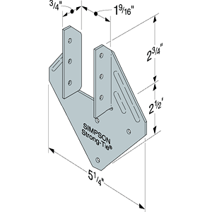
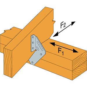
Thanks, I'm happy to see ideas that doesn't require the walls coming down. I'll await to see what Rod has to say before holding my breath though. If the cross member (the same one the HVAC guys notched) is not important structurally 2x6, 2x8 or larger beams could be placed overhead to support the ceiling.
An update for today, no construction :cry: and I wasn't able to reach Rory before he stopped over this morning. Thankfully the Peerless mount for my plasma was recalled (due to a potential bad weld), so we took the 50" down and replaced the articulating arm. The day was not totally without progress. :D
Hopefully we can iron out all of the issues and get ready to ramp up again. I'm not sure how much more free time Rory has to offer in the short, and much of this is more than a one man job.
Thanks again for catching these goofs. When we resume I will try and hold back the excitement and take it slow so we don't plow past any other mistakes.
Actually - I like the idea of the ledger board.......... it even makes up for another mistake (i.e.: read "code violation") and that is that the bearing walls do not have the pre-requisite double top plates........
Because of the fact that you are really only picking up 1/2of the load - the ledger will be fine.
Seismic isn't really an issue from my perspective.........
BUT - you cannot carry a load with 2x4 @ 16' - and adding another 2x4 to create an "L" is even worse - all you're doing in that case is adding more load to an already overloaded 2x4.
I see bad new on the horizon if you add a beam under this thing - from a code perspective..........
Mid span hangrs would probably be the best bet - but a real pain in the arse to institute at this point in time - they can't bear off the bottom chord.
And no - the mid span brace you cut is not a problem.
Rod
Yeah, the only thing that ledger board will do that is kind of uncool is that it will create an odd protrusion along the length of those walls when everything is finished.
But isn't this still moot, given the fact that the joists are too short (2x4) and too long? And what about the headroom -- 7' 6" from slab to bottom of truss? And what about the blocked window? And what about the hidden electrical service panel? And we haven't even talked about fresh air ventilation yet... :shock:
I also emphasize my disbelief about the "no permit required" thing.
Rod, what's your take on all of those issues? I don't want to overreact, but I really think I'm onto something... :roll:
--Keith :mrgreen:
Ya we figured that out once we started thinking about it.BUT - you cannot carry a load with 2x4 @ 16' - and adding another 2x4 to create an "L" is even worse - all you're doing in that case is adding more load to an already overloaded 2x4.
Do you think that cutting this brace in the same manner to allow 2x6 beams and add the ledger boards would offer the needed support Rod?Actually - I like the idea of the ledger board.......... And no - the mid span brace you cut is not a problem.
The idea in the post above should resolve these issues if Rod thinks it is ok.But isn't this still moot, given the fact that the joists are too short (2x4) and too long? And what about the headroom -- 7' 6" from slab to bottom of truss?
as shown in the picture above there is still an emergency egress window.And what about the blocked window?
I am interested in this as well.And what about the hidden electrical service panel?
New point, please explain.And we haven't even talked about fresh air ventilation yet.
looking into this as well.I also emphasize my disbelief about the "no permit required" thing.
NoI don't see that (making more cuts into that brace) as being an answer to your problem - one cut like I see in your pic is one thing - multiple cuts are another - that brace is required to ensure that the trusses act properly and don't collapse - it a part of their design - you can't just go around slicing it up. As far as the egress window goes - in most codes that's only a requirement for a sleepng area - basement windows aren't egress windows to begin with - so for me that is not an issue........ The thing with the electrical panel - if the treatment you put in front of it was hinged - with magnetic catches (for example) and you could open it with out the need for any tools - then it would meet the definiton of "readily accessible" - it isn't required for anyone who doesn't know the property to know where the panel is - just for those who would normally access it to know............ RodYa we figured that out once we started thinking about it.BUT - you cannot carry a load with 2x4 @ 16' - and adding another 2x4 to create an "L" is even worse - all you're doing in that case is adding more load to an already overloaded 2x4.Do you think that cutting this brace in the same manner to allow 2x6 beams and add the ledger boards would offer the needed support Rod?Actually - I like the idea of the ledger board.......... And no - the mid span brace you cut is not a problem.
BF, not all basement windows qualify as emergency egress. Do a search for "egress" to find the Portland build where authorities required one. It was quite an involved modification.
Rod, I know that emergency egress is required for sleeping quarters, but what about habitable space in basements? I was under the impression that some jurisdictions may require them in habitable (but not sleeping) rooms... :roll: ...Reference aforementioned project in Portland, Oregon.
--Keith :mrgreen: