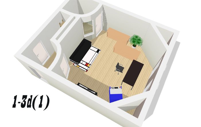
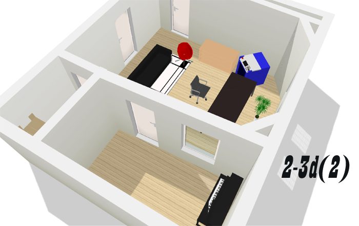
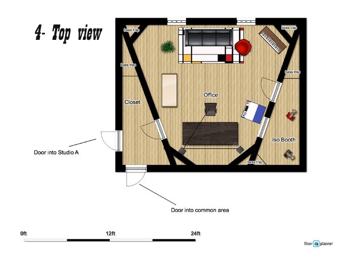
The mastering engineer is at the other end of this same building and has said that whenever people from studio A have put amps in our room to track them, he doesn't hear high frequency transmission through the walls but rather can feel and hear the bass through his floor.
Then a simple drum riser would probably be the answer. If you put an amp directly on the floor then you get direct transmission of the cabinet vibrations right into the floor itself. So all you need to do is to decouple the amp from the floor. The drum riser concept will do that, at low cost. I would try that first, before spending tens of thousands of dollars on floating your floor. You might still need to do that, but it makes sense to spend a few hundred first and see if that will fix the issue or not.
I don't have the details my contractor has planned exactly but the estimate includes OSB x2 layer... Rht 80 2in. I will try and get more information and cross-reference this and other posts on the subject to ensure it is as successful as possible.
Doesn't sound like there is anywhere near enough mass in that. Floated floors are usually done with concrete. That's the cheapest way of getting the mass you need.
One thing we were wondering is that if we do go with the second design, or any design that incorporates an iso booth for that matter, would it be OK to lay all of the flooring before framing for the iso?
Nope! For the very reason you mention next:
It seems intuitive to me that it would be better to make sure the planks of plywood in each space do not continue through the walls between cr and iso.
Exactly. There can be no physical connections between rooms. Technically, that is known as a "flanking path", which just means a route that sound can take to bypass your isolation as though it wasn't even there.
Having said that, we will likely only be putting 1 door to separate the iso,
That's fine, as long as it is massive enough and well sealed, and that you can live with the reduced isolation.
and won't be spending a ton of money on a quadruple pain window,
Excellent! Because quad-leaf is BAD for low frequency isolation, not good. Good isolation requires two leaves only. Not one, not three, not four: only ever two.
I think it would be worth it to lay the entire floor down first before framing (the iso). What do you think?
I think it would be a bad idea.
:)
I was referring to the measurements from the inside walls before working on layout of iso and closet, but after accounting for the space we would lose when soundproofing the wall.
I think you have missed the point about soubdproofing. That's not the correct way to do it. Let me explain.
To isolate properly, you need two "leaves" between you and the outside world, and also between each of the rooms. The only way to do that is to have a single "leaf" around the entire studio area, then build each room as another single leaf. If you were to build a two-leaf isolation wall around the entire area, and then build single leaf rooms inside that, you would have three-leaf walls to the outside world, which would REDUCE your low frequency isolation, not increase it. Yes, that sounds illogical and not intuitive at all, but it is the simple truth, and is a consequence of the way tuned isolation works. A 3-leaf wall is always worse than a 2-leaf wall for isolation, for the same overall mass and dimensions. And a 4-leaf wall is worse still.
The issue is this: It is a tuned system. If you start with a 2-leaf wall, then that is tuned to a certain resonant frequency that you set as low as you need to for your situation, by choosing the right mass and air gap. If you then put ANOTHER leaf next to that, well, you just destroyed the 2-leaf tuning that you had, and created 3-leaf tuning, which is based on different principles of physics, and different mathematical equations. The third leaf "re-tunes" the system to a higher frequency. And that's the problem.
Therefore, you must ensure that your existing structure is set up as ONLY a single leaf system. And you then need to add ONLY another single leaf system for each room. That's the way to get maximum isolation at minimum cost.
Of course, there are ways of compensating for a 3-leaf system, if you happen to have one: You can increase the size of BOTH air gaps and also add more mass to the middle leaf. But that involves extra cost for the materials, and also eats up valuable space for the additional air gaps. So the ideal thing is to build only 2-leaf walls wherever possible, since that is the most efficient and most economical way of getting good isolation.
I don't have plans at the moment. But I'm going to work together with him to get things firmed up.
You should definitely do that and post the isolation plan here, since it sounds like your builder is not planning on the cheapest method!
:) Draw your own conclusions from that ...
Isolation is a serious requirement in this build.
Then it definitely needs to be done right the first time. And since it is your money, it also needs to be done as economically as possible, without cutting corners.
The wall that is on the north side, or left side of the diagrams, is shared with the isolation booth of studio a. As I mentioned, the building is kind of weird in that it is actually 2 buildings backed right onto eachother. So what we have going for us on that wall is that there are infact 2 brick walls between the two spaces on that side.
Is there a decent sized air gap between those two brick walls? Is the gap filled with insulation? You might be luck there.... But it sounds like that wall might have to end up as three-leaf, or at least as a coupled 2-leaf plus a decoupled third leaf. There are solutions, but the problem has to be properly understood in order to define them.
The east and south walls are outside walls, and the south wall backs onto a common area where people hang out.
Great! Then those can just be simplified down to a single leaf, and perhaps beefed up to get the mass you need for the amount of isolation you need.
Well this is a new term to me, and I've been reading a bit about it. (Here's an intro link for any other fellow noobs...)
Yes, you do have to be careful about STC and TL! Two different things. STC is not a good way of measuring isolation for studios, since it does not even consider any low frequencies at all! The STC system was never meant to be used for describing studio isolation. It was meant for describing typical home and office isolation, where power low frequencies are not much of an issue, but they are in a studio! That's why the correct way of looking at studio isolation is with "TL" (Transmission Loss), not STC, and by looking at the full graphs, not just single-number summaries.
Reading it over I happily encountered what looks to be similar to what my contractor recommended for the walls if memory serves, which is : Double 5/8″ drywall on either side of a steel stud wall with insulation and 2 loads of Green Glue both sides.
Yes, that will work... provided that it is the ONLY wall in sight! In other words, you cannot build a wall like that right nest to an existing wall, since that would make ti a 3-leaf or 4-leaf system.
Maybe this will help to understand the issue better:
Image not preserved: MSM-walls.gif
Starting from the wall on the left: that is a typical house wall, with 2x4 studs and a single layer of drywall on each side, no insulation. The second one adds insulation for a small increase in isolation, from 33 to 36. Now the next one is interesting: build another identical wall next to the first wall, and you only get a very small increase in isolation: 40 instead of 36. Not much at all! The reason for the small increase is becuase that is not a 4-leaf wall, which is not a good isolator. However, if you then TAKE OUT one sheet of drywall from the middle of that wall, the isolation jumps greatly! By REMOVING mass form that wall, the isolation jumped a whopping 10 points. Because it not stopped being a 4-leaf, and turned into a 3-leaf. But look what happens in the next image. Once again, we TAKE OUT a sheet of drywall from the middle, and once again we get a big increase in isolation: 7 points. That's because we took a 3-leaf wall and made it into a 2-leaf wall, which is the optimum case. So even though the 2-leaf wall has only HALF the mass of the 4-leaf wall, it isolates nearly 100 times better. If you then make up that mass again, by adding a layer of drywall to each side, then you get another increase in isolation.
Compare the third image with the last image: Same total mass, same total thickness, same construction, but a major, huge difference in isolation. The ONLY difference is simply that one is a 4-leaf wall, and the other is a 2-leaf wall.
This is what I'm talking about. Building a 4-leaf is a bad idea, as it requires much more mass and much larger air gaps to get to a decent level of isolation. So do be careful about what design your builder comes up with...
And one other point: All of the above diagrams are talking about STC: If you compare the actual TL for those same walls, the effect is even greater: the 4-leaf is much worse in the low end of the audio spectrum, which STC does not measure...
:)
For this, I'm referring to the 4 walls that line the outside of this studio. We haven't talked about the iso walls yet as we just decided on adding that.
Ummmm.... in light of the above, you might want to re-think that! It is not correct to think in terms of "first we build a soundproof wall around our space, and then we build isolation walls for the rooms". That would be a mistake. All the walls interact, and work together. The entire place has to be built correctly as a 2-leaf system. If not, there are only two possible results: 1) You will end up with insufficient low frequency isolation, and your neighbors will lynch you, or 2) you will have good isolation, but will have spend MUCH more than you needed to, and will have wasted a lot of space in the walls to do it.
Basically, if Studio A hears me monitoring, this is all worthless.
Bingo! So design it right, build it right, and you will get there.
They will be micing vocalists etc in that iso that boarders on my studio and if I have to stop working everytime they're recording, then it's just not gonna work for anyone.
Yup!
So in practicality I guess I need to be sure that when I'm monitoring at 100 db in my studio when we finally nailed the mix and people wanna party, that the leak into studio a is next to nothing.
Yes, but you need to define "next to nothing" in terms of actual decibels levels. You can measure 100 dBC on a sound level meter, but you can't get that meter to show you what "next to nothing" is!
:)
After reading so much over the last couple days I'm feeling that this is a tall order. And I'm really happy to be able to get advice on this before we start construction.
It might be a tall order, or it might not. For example, if monitoring at 100 dB with an wall that gives you 60 dB of Transmission Loss (but not STC-60), you will be done to 40 dB on the other side. 40 dB is pretty quiet. But only you can say if it is "next to nothing" or not.
It seems as though the walls we plan to build, if they do carry an STC of over 60 along with the two cement walls will do quite a good job on transmission.
Perhaps not, if you end up with a 4-leaf system! Refer to the diagram above...
This is a common misconception for people still trying to get their head around the concept of walls being tuned systems: Building additional walls next to existing walls does NOT necessarily increase isolation in the low end. It will certainly increase high frequency isolation! No doubt about that. But not low frequency isolation. And that's where all your problems will be.
Any way of estimating that?
Yup! With the equations for 2-leaf and 3-leaf walls, and the equations for mass law. And there are also plenty of research documents on this issue that you can use to find the best structure for your requirements and your budget. IR-761 is probably the best, and the famous Wyle-73 report gives all the background you could ever want on why things work like they do.
Maybe you can correct me that it still is inadequate to what I'm hoping to achieve.
You CAN achieve it, undoubtedly: The question is do you have enough money to achieve it. The very best isolated studio in the world (Galaxy Studios) is rated at over 100 dB of isolation, so your 100 dB monitoring level would be practically zero dB on the other side, making it not only much quieter than "inaudible", but also virtually undetectable, even with sensitive laboratory instruments. So it can be done, but that cost them a huge amount of money, and required hundreds of tons of concrete to achieve. And even so, they did it all with 2-leaf walls, since that was the lowest cost way of doing it.
But 100 dB of isolation is total overkill for the type of studio you are doing.
OK, there's something else that you need to keep in mind: the dB scale is logarithmic, so things get easier and easier as you go down. If you shoot for 90 dB instead of 100 dB, well then you only need to isolate one tenth of the energy. Or if your goal is 80 instead of 100, then you only need to stop one hundredth of the energy. And 70 dB as compared to 100 dB means stopping on one thousandth of the energy.... Finally, some good news for you!
:)
It seems to me that the doors are probably going to give us the most grief on that wall. I've read over design links to DIY doors and seen other posts talking about 5000$ doors. In this case, the DIY option is the only one.
Yes, very true. Commercially bought acoustic isolation doors are EXPENSIVE!!! And you really can build your own much cheaper.
This thread covers some interesting options.
Yup. You might want to buy Rod's book to see what they are talking about there. He also shows some other options, as well as his famous "superdoor".
I didn't come across the STC for Rod's DIY leadcore doors. Does anyone know off hand? Or John Brandt's Sand-core doors? Are they published anywhere? Any estimates?
Probably not, since the final isolation level of a door depends so much on the seals around it. Even Rod's superdoor will give lousy isolation if there are no seals. The seals are critical.
I'm not as concerned with the other set of doors opposite the speakers. That common area is often filled with sound from studio a, not overwhelming, but audible. Of course I want to get good isolation through there as well, and I am especially concerned with low frequency transmission into the mastering studio that is about 30 feet away,
I wasn't talking about moving your door for isolation purposes, but rather for getting the room acoustics right. If the door is in the middle of the rear wall, then you cannot put the acoustic treatment that is needed at that that location.
Also, you should start thinking of the room as a single entire unit, not as individual parts that need more isolation here or less there. In reality, the TOTAL isolation of the room is exactly as good as the weakest part. So if you have four walls done to 70 dB of isolation, but one of your doors is only good for 30 dB, well then the total isolation is only 30 dB! Meaning that you wasted a huge amount of money on getting the walls to 70 dB, when all the needed was 30....
:)
We have a decent, separate budget for doors, exterior walls, electrical, interior design, and flooring, insulation, electrical etc.
Great! You had me a little worried there with such a low budget! That sounds far better.
And don't forget HVAC: That's a major part of any studio, since installing the vents implies cutting huge holes in your expensive perfect isolation walls.... so the HVAC system needs careful design, especially for the silencer boxes that retain the isolation while allowing air flow.
What would be the criteria upon which we plan those diffusers? you mentioned that on design 2 you would put a big absorber flanked by 2 superchunks on the back wall, could the diffuser hang from the wall with the absorption built in?
Diffusers that are based on numeric sequences exhibit a problem called "lobing", which basically means that they don't really spread the sound around evenly in all directions. There are "lobes" of higher intensity in specific directions. And it is not just lobes of intensity, but also lobes of phasing and timing and frequency issues: It gets complicated...
It takes distance for those lobes to even out, smooth over, etc.
So if your head is too close to a diffuser, you are not hearing a true diffuse sound field, but rather a messed-up, colored, phased, time-delayed, intensity modulated muddle of sound! Clearly, that's not good.
So, that has to be taken into account when designing the room. Diffusers have to be positioned sufficiently far from the engineer's head that the lobes are not an issue.
Then, the diffusers themselves should be designed to that there cut-off frequencies are correct for the needs of the room itself: For example, it makes no sense to only diffuse above 4kHz if the room has specular reflection issues at 1kHz. etc. the diffusers need to be designed correctly to do what is needed in the room, nothing more, nothing less.
The also need to be placed where they do the job they are designed for, and where they do not interfere with the direct sound path around the engineer. Etc. Etc. Lots of things need to be taken into account when designing a room!
Also I was wondering if the corner bass traps you prescribed on that back wall should have the same hypotenuse? Do the dimensions of the trap correspond to the potential problematic room modes? if so how?
Not really. The bass traps are broadband, which is the best approach. The actual shape can vary as needed to fit the room, but the general idea is to make them BIG and DEEP. About 36" across the front face is the general recommendation: The bigger they are, the better they cover the low end. They don't need to be identical, and it is not necessary to get the, to exact 45° angles across the corners: 30° is fine, and so is 60°, or anywhere in between. Shape is not critical, since we are talking about waves that are many feet long anyway.
There are other types of bass traps that can be tuned, but that's generally not necessary, unless you have specific stubborn problems AFTER doing general broadband trapping. It is hard to tune acoustic devices anyway, and the lower the frequency, the harder to gets. So broadband is the best approach, followed by tuned devices as a last resort.
I entered the data into this room mode calculator
http://www.bobgolds.com/Mode/RoomModes.htm And while I was happy to see mostly green and only a couple yellows
:lol: I'm not quite sure how to interpret that data.
Great! That's the best calculator on the internet, IMHO! It gives you oodles of very useful data. But as you say, not so easy to interpret. OK, scroll down to the part where it says: "Computed Information". Right under that is a section called "R. Walker BBC 1996:" with three calculations. If all three of those say "pass", then that's a really good sign. Next look at "Nearest Known Ratio:". If the number before the bracket is less than ten, that's another good sign: it means you are close to one of the ten best room ratios.
Now check "Volume:" Anything over about 1500 cubic feet is good, and over 2500 is great. NExt: "Surface Area Floor:" More than 220 is good, more than 320 is great.
Finally, scroll down to the Bonello diagram at the bottom: it it looks like a picture of the Andes mountain range,, then that's bad. If it looks like a smooth curve, low on the left rising exponentially to the right, then that's great.
OK, there's a lot more in there that is really important, but those are your basic indicators.
Are those modes completely irrelevant because of the splay?
Yes. No. Maybe.
:) Hard to give you a definitive answer here: Splaying walls means the the axial modes associated with that pair of walls cease to exist. However, the tangential and oblique modes are still there, and not much different. And all modes that do not involve those walls remain exactly the same. So for example if you splay your side walls, then that has no effect at all on the front-back axial modes, nor on the vertical axial modes (ceiling-floor). It has some effect on tangential modes that happen to involve the side walls, but no effect on the tangential modes associated with the ceiling, floor, and front and rear walls. It also affects all oblique modes to some extent as well.
But if you also splay the ceiling, things change again
Large splay angles also affect the modal response much more than small splay angles.
So there's no simple answer to your question. "It depends" is all you can say.
Having said that, it still makes sense to plug in the average dimensions of the room, ans get a rough idea of what will be going on. It won't be accurate, but it will still be useful.
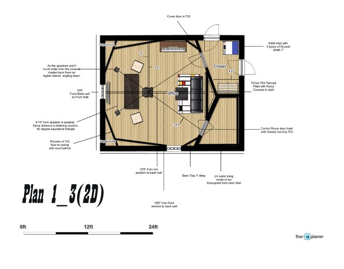
I've included a revised plan including dimensions of plan 1.
But now you made the rear wall concave! Concave shapes focus sound. And if you take a close look at what you did, the rear walls are no angled perfectly to proved direct reflections right back at the ears of the engineer!
:shock: The left speaker faces the right rear door head-on, so sound from that speaker will be reflected back at the engineer's right ear. And vice-versa for the right speaker. Not a good situation!
the design was inspired by other RFZ rooms I have found plans for on this site and others.
OK; but yours is not working out as an RFZ: you clearly have first order reflections coming off the side walls, directly at the engineer...
:) try ray-tracing, and you'll see what I mean.
I'm now down to 1 or 2,
2 still looks best to me. And the new version is an improvement over the previous version. Except that you have angled your speakers too much: they are now at a 90° intercept, instead of the more normal 60° intercept. I would suggest keeping moving them to a 60° intercept again, as there's no need to go for such a wide angle in your room: you have enough space to do it right.
You also mention a downwards angle for your soffit mounts, but that is seldom necessary, unless you have a very large meter bridge or something else in the way. You can't angle more than 10° anyway, and even that will give you problems with reflections off the console and/or desk. So just mount them vertically, not tilted, and with the acoustic axes at 1.2m above the floor. That's the "standard" height and configuration for a control room.
Interesting. I love hearing things like hands down and no question, in amongst all the confusing litterature!!
Yeah, that's one of the few places where you actually can say that! Leaving speakers out in the room is fine, of the room is big enough that you can get them faaaarrrr away from the front and side walls. But not many rooms are that big. So in the majority of reasonably sized rooms, the speakers are close to both the side walls and the front walls, meaning that there are multiple bad things going on SBIR, comb filtering and other types of phasing issues, as well as edge diffraction, first reflections off the front walls, and many other things. But out the speakers in soffits, and all that just goes away. Since the speakers are no longer inside the room, acoustically speaking, the simply cannot possibly interact with those walls front and side walls! They can only interact with the ceiling and floor, and the rear wall, but if those are treated suitably, then they too "disappear" acoustically, to a large extent. soffit mounting just makes sooo much sense.
At the moment, I'm not completely sure I'll be keeping the same monitors I currently own. I'm going to try a few sets in the coming months, so the dimensions of the mounts may change. I suppose those recesses could be changed to fit new speakers over a weekend or so if I do decide to change. I'll have to read more and give it some thought.
Barefoot posted a design here once for soffits where it was very simple to remove and replace the actual speakers, quickly and easily. Wotth looking or that!
Cool. Is the MSM frequency of the spacing on the doors equivalent to the spacing between the inner and outer layers of the wall?
MSM is a function of both air gap AND mass. So if you decrease the air gap at some point in the wall, then then mass must increase by the right amount to compensate. The basic idea of an MSM wall is to try to keep the mass (surface density) and air gap
There's another is here: The insulation in the wall cavity is a major part of the MSM system: it acts as a damper on the resonance, and increases the average path length that a sound wave "sees" as it travels across the gap. Mathematically, the path seems to be 1.4 times longer through the insulation, which increse the isolation as well, as it lowers the MSM resonant frequency . But you cannot put insulation in the windows! You sort of want to see through those, so the simple fact of NOT having insulation between the two leaves of glass means that the isolation is reduced. So you need to increase the mass of the glass to more than you think you need, or make the gap between the two panes bigger, or both. And the same applies to doors, to a lesser extent: you can have some insulation attached to the backs of the doors, but you can't fill the cavity. So doors need more mass, and bigger gaps, than the walls they are in.
I found this stuff, it looks like it would be good for our needs and get us a long way to sealing gaps.
Looks good. Also take a look at the stuff that Zero International has to offer.
Are there formulas I can use?
Yup!
Image not preserved: MSM-equation.jpg
(Not sure where I got that from: If someone knows, please tell me so I can add the copyright info).
Is there a way of figuring out what the optimal splay angle would be in a room this size for RFZ?
Yes: by raytracing. Search the forum for info on how to do that.
Is there any way of calculating modes for splayed walls? Is this no longer simply about ratios?
Yes, but it ain't easy! You need to resort to computationally intensive FEM/FEA analysis, which means you need an operator who can take your 3D design and set up the correct boundary conditions, run the analysis, and analyze the results for you. Not something most home builders want to bother with. And not necessary either.
One thing I'm not certain about is what to use for the side walls that are splayed and run from the front to back of the CR. Should they be absobtive? Can they be drywall?
Slot walls are best, but if you have first reflection issues, then you should put thick absorption at those points. Of course, if you do a true RFZ design, then it would be impossible that you have first reflection points on the side walls....
I'd rather the studio not be completely dead.
Exactly! Here too you should follow ITU specs. The idea is to aim for neutral acoustics, neither live nor dead, and following the frequency contours.
Is the 18 feet from front to back in 1 or the 19 in 2 enough to use a diffuser on the back wall?
The Haas time is around 20ms, so you need enough distance that no first order reflections hit your ears within 20ms of the direct sound. But for diffusers, it is different: the distance depends on the tuned frequency of the diffuser: You need a distance of at least three full wavelengths for the lowest cut-off frequency of the diffuser, and really you should calculate down to half of that (twice the distance), since most numeric based diffuser still scatter down to about one octave below the cut-off frequency.
- Stuart -