hi,
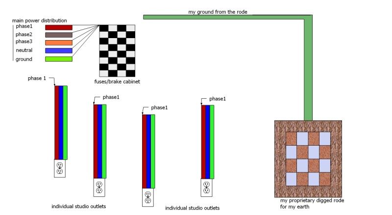
i am from macedonia. at the moment i am visiting some friend who can help me with a design of electricity distribution for my future studio. i have to admit that i read through posts here, and what i firstly understood is that i have to connect my proprietary digged ground rode to the electrical leg of audio equipment. therefore, that MY ground is NOT to be interconnected with incoming main distribution ground. in another words, all my studio logic outlets will connect to the neutral from incoming power, to the phase (phase1) from incoming power AND to the my ground (and not to the incoming ground)...
ok fine, but then i read further and one poster mentioned that proprietary ground HAS to be connected to the incoming main distribution ground and bridged with neutral (also from incoming main distribution)...
thats where i lost it altogether...
what is already done:
a) a rode diged inside the soil (far right in my picture)
b) incoming main distribution three phase tick cable (top left) is in the place
c) main fuse break cabinet (black and grey grid) is placed on the wall
d) copper cable from the rode is brought to the main fuse break cabinet
e) all studio logic power outlets (audio processors, console, screens, computers, speakers, etc...) are marked and designated to phase 1
my questions are:
1)
what i have to do next... connect all studio logic outlets to the phase and neutral from incoming power distribution and to the incoming main power ground AND my proprietary ground OR only to my proprietary ground?
2)
do i need to have separate fuse break cabinet for HVAC and lighting and apartment?
THX,
pic attached,
cheers and many thx,
d.
1. If the outlets are individually wired, each to it's own breaker, then the green wire in your cable should suffice, as the grounds runs are also individually run back to a common bus. However if multiple outlets will be connected in parallel (which is the typical case) then the green wire should be used only for grounding the duplex box if these are metal, otherwise it can be clipped and insulated at the box, and a separate ground wire should be run from each outlet back to a common point - usually the ground bus in the breaker panel. The common point can however be a separate (local) grounding bus panel, but should nonetheless be connected to the main panel ground as well as your rod.
2. A separate breaker panel should not be necessary but it is good if the outlets in your studio can be on their own phase.
HVAC and basically anything with motors or dimmers should definitely be on a separate circuit and even better on a separate phase.
STOP!!! The Ground Rod or the other types of connections to Mother Earth are for safety! All the ground wires (PE,EGC) must be connected at the point where electrical power enters the building (Service Entrance), all the wires to Mother Earth must be connected at this same point. In a correctly wired building, the connect to Mother Earth will have very little impact on the audio quality. (It only impacts audio quality if there are already wiring errors.)
Please read the papers below before starting your project.
(Yes it's over 150 pages, but well worth reading)
The Jim Brown of Audio Systems Group white paper:
"Power and Grounding for Audio and Audio/Video Systems"
http://www.audiosystemsgroup.com/SurgeXPowerGround.pdf
The Bill Whitlock of Jensen Transformers Seminar paper:
http://www.jensen-transformers.com/an/g ... eminar.pdf
"Power White Paper" from Middle Atlantic.com:
http://www.middleatlantic.com/power.htm
or a different version of the same paper
"The TRUTH" from ExactPower of Middle Atlantic Products:
http://www.exactpower.com/elite/wpapers.aspx
1. If the outlets are individually wired, each to it's own breaker, then the green wire in your cable should suffice, as the grounds runs are also individually run back to a common bus. However if multiple outlets will be connected in parallel (which is the typical case) then the green wire should be used only for grounding the duplex box if these are metal, otherwise it can be clipped and insulated at the box, and a separate ground wire should be run from each outlet back to a common point - usually the ground bus in the breaker panel. The common point can however be a separate (local) grounding bus panel, but should nonetheless be connected to the main panel ground as well as your rod.
i am going to have outlets in a group of 4 (just like those extension cables, just in an outlet form).
one cable (3x2.5mm²) is handling that group of 4 outlets. so 1 green ground wire goes from them to the breaker panel. is that OK? or u are trying to say that beside that (3x2.5mm²) cable i need to bring 4 more individual wires for grounding all 4 outlets within a group?
2. A separate breaker panel should not be necessary but it is good if the outlets in your studio can be on their own phase.
HVAC and basically anything with motors or dimmers should definitely be on a separate circuit and even better on a separate phase.
they will be on a separate phase definitely, but within same breaker panel...
can u suggest what would be the best scenario according to my picture? what to connect with what, so i can come to my electrician with some suggestions as he is not in studio business... do i have to connect digged rode ground (dark green) with incoming main ground and all greens from individual lines to them? in one word, all three green kinds together at the breaker panel?
many many thx,
d.
STOP!!! The Ground Rod or the other types of connections to Mother Earth are for safety! All the ground wires (PE,EGC) must be connected at the point where electrical power enters the building (Service Entrance), all the wires to Mother Earth must be connected at this same point. In a correctly wired building, the connect to Mother Earth will have very little impact on the audio quality. (It only impacts audio quality if there are already wiring errors.)
Please read the papers below before starting your project.
(Yes it's over 150 pages, but well worth reading)
The Jim Brown of Audio Systems Group white paper:
"Power and Grounding for Audio and Audio/Video Systems"
http://www.audiosystemsgroup.com/SurgeXPowerGround.pdf
The Bill Whitlock of Jensen Transformers Seminar paper:
http://www.jensen-transformers.com/an/g ... eminar.pdf
"Power White Paper" from Middle Atlantic.com:
http://www.middleatlantic.com/power.htm
or a different version of the same paper
"The TRUTH" from ExactPower of Middle Atlantic Products:
http://www.exactpower.com/elite/wpapers.aspx
wow, Speedskater,
thx so much for the links.
i have to admit i get lost after 10 or so pages.
i will try to work on this... but i am not sure if i really need myself to understand it all as i am more of an artist.
however, i will certanly read through it and try to catch as much as possible.
i will kindly ask u if u can comment on what i wrote up there to previous poster about where and how to connect "three different kinds of greens". i know that nobody like to recommend something like that, but i am assuring u i am not going to blindly follow anything myself without electrician. i just like to hear opinion based on a drawing up there.
thx so much...
d.
Yes in this case each receptacle will require a separate ground wire in addition to the 3 conductor cable. These separate ground wires must be wired directly from the ground pin of the receptacle to the ground bus of the panel - each individually. Do not wire them from receptacle to receptacle as you will the power cable!
do i have to connect digged rode ground (dark green) with incoming main ground and all greens from individual lines to them? in one word, all three green kinds together at the breaker panel?
You got it - 4 kinds actually. (What speedskater said regarding bonding the service ground to the rod at the service entrance is correct.)
the ground from the service, from the rod, the greens of the 3 conductor cables (one per circuit) plus the individual groundwires from each receptacle.
so 1 green ground wire goes from them to the breaker panel ... beside that (3x2.5mm²) cable i need to bring 4 more individual wires for grounding all 4 outlets within a group?
Yes in this case each receptacle will require a separate ground wire in addition to the 3 conductor cable. These separate ground wires must be wired directly from the ground pin of the receptacle to the ground bus of the panel - each individually. Do not wire them from receptacle to receptacle as you will the power cable!
do i have to connect digged rode ground (dark green) with incoming main ground and all greens from individual lines to them? in one word, all three green kinds together at the breaker panel?
You got it - 4 kinds actually. (What speedskater said regarding bonding the service ground to the rod at the service entrance is correct.)
the ground from the service, from the rod, the greens of the 3 conductor cables (one per circuit) plus the individual groundwires from each receptacle.
so 1 green ground wire goes from them to the breaker panel ... beside that (3x2.5mm²) cable i need to bring 4 more individual wires for grounding all 4 outlets within a group?
Yes
wow,
i am soo confused now, but also i want to understand it correctly:
so, my outlets have 4 receptacles (for powering 4 devices) in a group.
1.power cable AND neutral will go from receptacle to receptacle.
2.proprietary ground cable will not go from one receptacle to receptacle but each will have its own cable from receptacle to the common ground buss at the fuse cabinet?
3. what do i do with ground green cable that comes to the outlet with phase and neutral???
i am really confused why it is not correct to use just that within 3 wire cable without propietary extra wires for the ground... please bear in mind that i really want to understand and i believe u, ofcourse...
can i have more than 1 outlet with 4 receptacles (in my case they are in a group of 4) on a same fuse/breaker?
THX!
d.
ok,
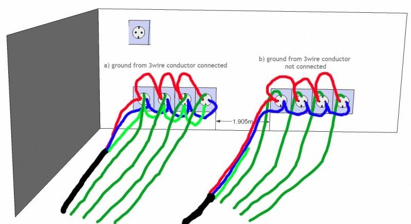
to make it clearer, as my english is not the best, i made a quick ugly drawing...
thats how my outlet with 4 receptacles is configured.
live, neutral (left, right) and ground touch (up and down) in each receptacle.
dark greens - proprietary extra ground lines
light green - "internal" 3 wire cable ground
which version is correct, a) or b)?
i guess u will say a), but then i do not understand what is a benefit of having individual lines... please help...
what is then situation when u use in studio extension outlet cable??? surely, ther eis just one ground bridged there?
and dont laugh for a drawing :)
Now your drawing is throwing me a curve.
In your original graphic you showed four separate duplex outlets. I assumed these (group of four to the circuit) would be distributed around the room. Your new drawing shows all four 'sockets' side by side, as if in a single panel. If the latter depiction is correct then you should be allright with plan (a) ground from 3-Wire conductor connected because the distance between plugs is negligible hence the Potential Difference between outlets is a nonissue.
If the individual sockets are distributed around the room however, then (b) would be the way to go.
I know it seems almost counterproductive and nearly downright stupid to wire in this fashion, but the concept is "Star Grounding" which you can look up on the internet, and the idea is to help prevent ground loops caused by potential differences between different grounding points in the studio. I mentioned previously that this grounding scheme can be terminated in a separate local 'grounding panel' which I personally find preferable, particularly if the mains panel is far away. This local bus is connected to your system ground, i.e. breaker panel ground, but the important point here is that all the grounds in the room are referenced to the same physical point - minimizing the issue of potential difference.
The green wire in the 3-wire cable is for safety and should be used exclusively for grounding conduit, the housing or installation box in the suggested star-grounding concept. If the said housings are plastic, then this wire can be clipped and insulated at the termination point but should be connected nonetheless at the main panel.
If you can have a look at the book Home Recording Studio Build it Like the Pros by Rod Gervais often mentioned here, there is a diagram showing this wiring concept (at least in the second edition).
P.S. If you have AV equipment (e.g. satellite receiver, or cable box etc) or a stereo receiver in your studio, be careful as these usually have their own ground reference point and will very likely have a potential difference which will most assuredly introduce problems if plugged into your studio circuit and will require isolation. But that is another theme.
I have a question:
How does the power wiring get from the breaker box to the wall outlet?
In the US some homes and many commercial building have metal tubes (conduit) with individual Hot, Neutral and Ground wires inside.
But most homes have a 3 conductor plastic cable.
BriHar,
i think we will finally understand each other, or should i say, now it makes all more sense to me, and maybe i was not totally precise about all... will answer bit later as i am too busy right now...
Speedskater,
will answer a bit later...
thank you guys for great help!
:yahoo:
hi,
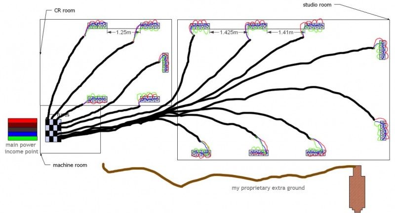
ok, here is a (somewhat simplified but better than previous) drawing of my situation.
when i talked about group of 4, i talked about 4 receptacles in a row (sorry about my english, that's also an issue here )...
the first time i talked about this i sent a drawing with ready-made outlets from Google sketch-up library and there was only with 2 of them :)
now, this shows an rough position of my control room, studio and very small machine room where also fuse panel is located.
all cables are 3x2.5mm² cables with hot, neutral and ground enclosed in some kind of semi-thick plastic/gum.
as i on the top i will have apartment, i have 2 separate fuse panels.
it is like this:
main power 3phase income is located in machine room 5x5mm²
one cable 3x3mm² feeds from there and departs upstairs to apartment where all the fuses of apartment are located, for this phase nr. 3 i used
fuse panel in machine room handles all fuses from studio and control room
all audio gear + logic (computers, monitor screens, etc...) is on phase nr. 1
all lighting and aircones and ventilation and few outlets used for vacuum cleaner, etc are on the phase nr.2
question 1: do i need to have all 4 receptacles within 1 outlet group on a same fuse? (all mine are in group of four, this time exaclty as on the picture)
question 2: is this what i have on my picture star grounding, EVEN WITHOUT EXTRA WIRE FROM EACH RECEPTACLE as BriHar suggested? when first reading his kind answer i couldn't understand why on the earth i would need another cable just for ground if (as he later pointed out from my pic) distance is so small.
can i leave it like this???
question 3: so i do not need extra wire for ground? (just to make it definitely sure to myself) 8)
question 4: what do i do with my digged ground rod? today i talked with one audio consultant and he pointed that area where i am is pretty dry and rocky, stoned... so, he says that my ground is never going to be as it should be, in other words he is sure that btw main power distribution ground and this my ground is going to be a potential difference that will not be acceptable... he says, that as i have, new modern installation, he will go only with main power grounding for a start, while having my ground just in a stand by to experiment if needed.
he also strongly suggests to purchase online UPS device of 2 kW for audio phase 1.
question 5: any problems with having a wireless router and switch in a very close proximity of a console desk and rack outboard?
guys, many thx..... i am an artist and just a bit technical person...
thx a million for the help!!!!
For US readers "3x2.5mm² cables" are about 13AWG wire.
And "one cable 3x3mm²" is just smaller than 12AWG.
Let me get back to this tomorrow, if the grandson doesn't interrupt all day.
OK - there is nothing that should be confusing here......
Let's just deal with one group here - the rest would be the same - so no reason to get things cloudy because of multiples.
If you are using plastic or fiberglass boxes:
You have 4 outlets sitting one right next to the other - and all 4 are going to be powered from the same circuit breaker.
In order to install "star grounding" for these you will need the following:
From the breaker you will connect the "hot leg" - which you will daisy chain from one outlet to the next.
From the neutral buss on the panel you will connect one neutral leg - which you will daisy chain from one outlet to the next.
Now you will have to bring 4 individual ground wires - one from each outlet - back to tie into the electrical main grounding wire. You connect these to the receptacle ground.
You can bring these to a new box outside of the main panel - where they will tie to a grounding buss - and a single wire from that which will be tied directly to the ground wire between the main panel and the ground rod.
If you are using steel boxes things change a little bit:
You have to begin with Isolated Ground Receptacles. These have 2 separate points to attach ground wires.
The hot leg and neutral are the same as above.
There is a common ground wire that runs form the ground buss in the main panel - which you will daisy chain from one box to the next. You must also attach this to the body ground of the receptacle.
Now you will have to bring another 4 individual ground wires - one from each outlet - back to tie into the electrical main grounding wire.
The grounding in either case is the same.....
SO in the first case (Using non-metallic boxes and standard receptacles) you would have 6 wires required for the install - and in the 2nd (using metallic boxes and isolated ground receptacles) you would require 7 wires for 4 outlets.
Under no circumstance should you ever use a separate ground rod for this system......
I hope this helped simplify things.
Rod Gervais
GIK Acoustics
Director of Education
http://www.gikacoustics.com (USA)
http://www.gikacoustics.co.uk (Europe)
Tel.(US)[removed]
Tel.(UK)+44(0)20.7558.8976
Now you will have to bring 4 individual ground wires - one from each outlet - back to tie into the electrical main grounding wire. You connect these to the receptacle ground.
sorry, i connect WHAT to receptacle ground and what do you mean exactly by receptacle ground?
You can bring these to a new box outside of the main panel - where they will tie to a grounding buss - and a single wire from that which will be tied directly to the ground wire between the main panel and the ground rod.
so, i ignore the third wire (grounding) in a cable that goes from breaker towards panel with 4 outlets in a row?
just like on my second picture in this thread, part b) ? [grounding2 copy.jpg]
i understood BriHar i can daisy chain this ground too, as distance is negligible?
so u are suggesting installing small panel just for these grounds and connect that ground buss via cable with main fuse panel ground buss?
only part i do not understand is what do u mean by "ground wire btw main panel and ground rod"? how we came now to the ground rod? are u referring to my extra rod digged into the soil?
SO in the first case (Using non-metallic boxes and standard receptacles) you would have 6 wires required for the install -
again, exactly like on mine second picture part b)? [grounding2 copy.jpg]
Under no circumstance should you ever use a separate ground rod for this system......
so, why u mentioned rode above?
please do not consider me as a bugger, i just really really try to understand.
can you please explain what would be wrong with situation as on my last picture [grounding3 copy.jpg] where ground is daisy chained? i always understood that only thing that matters is that we have only one SAME path to the ground.
now it seems that distance btw outlets is also important, i am just not sure how?
i did my "homework" and did read through various forums, but every now and then i find contradictory information's which confuses me even more.
and, at the end, do you and BriHar agree on this (see above) matter and i do not follow you guys, or you have opposing opinion?
thank you SOOOO much.
OK, nice to see Rod popping in here.
I also have to question whether it is imperative that each outlet have a separate ground run back to the bus if they are physically side by side in a box. With a duplex outlet there are 2 outlets sharing the same physical ground terminal. I also look at this from a practical viewpoint and consider that powerbars are going to inevitably be plugged into these outlets. In fact my desk has powerbars built into it - maybe I've been lucky, but I've never had a problem. My last studio was a worst case - no ground wire at all :shock: all ground lugs on the outlets were bridged to neutral with jumpers. Well I took the bridges out, bolted a waterpipe ground lug onto a feedpipe of the radiator (I know, it should have at least been a cold waterpipe- but there weren't any in the room) and referenced each receptacle (duplex and triplex) separately back to this grounding lug (The integrity of the house ground and waterpipes was excellent according to an electrician who checked it out). From there, the rest was powerbars (also there was a UPS for the PCs and a Voltage regulator).
Anyway...
to your questions earlier Delfin,
1. I assumed this is what you will do, it makes the most sense.
2.we'll wait and see if Rod replies before making a definitive decision.
3. Since your conduit and boxes are plastic, then no you won't require the ground for this.
4. Do as your consultant suggested. Regarding the UPS, not necessarily for the audio circuitry, some of these can cause noise! Besides, why do you need UPS on the desk?. Best to use it only for the PCs, where it makes sense to do an automatic shutdown in a power outage. You might want to put a (good quality) power conditioner on the desk supplies though.
5. Nobody can answer that question definitively for you. It might, it might not. If in doubt, put them as far away as possible.
Ah! Perhaps I missed Ron's point.
Did he mean:
In the 'group' box, bring four short wires from the ground terminal of each outlet and tie these to the ground wire of the 3 wire cable from the mains, using perhaps a marr connector?
OK - let's deal with language barriers if we can.....
The box is the container installed in the wall that the wires run into.
The receptacle is what you plug your gear into.
So when I say plastic or metal box - this is not referring to the receptacle........
Look below - this is a simple diagram for a star grounding system.
This diagram is what you would do if you were installing the outlets (receptacles) into plastic wall boxes.
I also have to question whether it is imperative that each outlet have a separate ground run back to the bus if they are physically side by side in a box. With a duplex outlet there are 2 outlets sharing the same physical ground terminal. I also look at this from a practical viewpoint and consider that powerbars are going to inevitably be plugged into these outlets. In fact my desk has powerbars built into it - maybe I've been lucky, but I've never had a problem.
Bri,
Speaking technically (not practically) each individual outlet has an individual ground that runs back to the ground going to earth.
My example of 4 outlets side by each was just to attempt to make the illustration easier to picture.
However - from a practical point of view you could group outlets installed in a common box - althuogh I personally would not install the wiring in that manner......
That is *(after all) the whole concept of star point grounding - you spend additional money to purchase hospital grade I.G. receptacles specifically because they have a ground point (for the plug) that is isolated from the ground for the body.....
My last studio was a worst case - no ground wire at all :shock: all ground lugs on the outlets were bridged to neutral with jumpers. Well I took the bridges out, bolted a waterpipe ground lug onto a feedpipe of the radiator (I know, it should have at least been a cold waterpipe- but there weren't any in the room) and referenced each receptacle (duplex and triplex) separately back to this grounding lug (The integrity of the house ground and waterpipes was excellent according to an electrician who checked it out). From there, the rest was powerbars (also there was a UPS for the PCs and a Voltage regulator).
You got lucky is all I can say......
Not from a grounding (safety) point of view - but from a noise point of view.
The heating systems for homes, along with the water pipes - are required to be bonded to the electrical panel.
The water services are also often steel or copper feeds coming in to the building from underground - which means they are also a source to ground.......
Ground loops are caused by different sources to ground that have different potentiality.
It is because of the possibility of different sources to ground (within the same building) - and the different potential they have that we bother with star grounding to begin with.
Rod Gervais
GIK Acoustics
Director of Education
http://www.gikacoustics.com (USA)
http://www.gikacoustics.co.uk (Europe)
Tel.(US)[removed]
Tel.(UK)+44(0)20.7558.8976
hey guys,
thank you so much for your clarifications...
after long discussion today with my electrician, i think i will go with the scenario on my last pic...
i talked with 2 other studio owners and they confirmed that i should be fine with it...
i also explained all our conversation here...
regarding the water pipes...
in old houses, i can imagine that u can run into situation where metal pipe was somewhere "eaten" by corrosion... if that part is replaced, any grounding becomes a failure... so, probably one thing to check...
in new houses we are using now exclusively fancy plastic water-pipes with some even fancier protection shield (some foam)...
once again, thx so much...
if i run into additional doubts, i will feel free to ask...
cheers,
d.